The Arduino does not come with a display, and that’s perfectly fine as it’s intended to be used as a micro-controller and not a micro-computer.
Adding a display however, may be needed at times though to provide user feedback for when a user is using your marvelous Arduino invention.
User feedback can be done in several ways of course: a simple beep, a simple LED, a simple LCD screen, or like in this case, a more advanced Color Display.
Considering the price I decided to get one ($20 at Amazon, $13 at SainSmart, starting at $13 on eBay, or an Arduino version at AdaFruit for $20) and experiment with it.
Ad Blocking Detected
Please consider disabling your ad blocker for our website. We rely on these ads to be able to run our website. You can of course support us in other ways (see Support Us on the left).
SainSmart 1.8″ Color TFT LCD Display for Arduino
This 1.8″ display, can display 128 x 160 pixels, is capable of displaying 262,144 (18-bit) colors, measures 5 cm x 3.5 cm, and is about 6 mm thick.
The display has back-light and comes with a Micro-SD-Card reader (supporting FAT16 or FAT32 formatted Micro-SD-Cards).
The display is driven by a ST7735R controller ( ST7735R-specifications.pdf (2.1 MB) ), can be used in a “slow” and a “fast” write mode, and is 3.3V/5V compatible.
It’s size, and display qualities, makes this a very desirable display for use with the Arduino, or even Raspberry Pi (as shown on this website).
This article is written with the SainSmart/Amazon version in mind – the pin-out of the AdaFruit board is slightly different!
I illustrate the differences in the tables, so please pay attention.
Note : The Shield version by AdaFruit also has a 5 direction “joystick” on board.
SainSmart – 1.8″ TFT LCD Color Display for Arduino
Arduino Libraries
To save you a lot of time developing applications (Sketches) that use the display, both SainSmart and AdaFruit offer very helpful libraries.
Since the libraries offered by SainSmart can be confusing for beginners, we will use to the Libraries offered by AdaFruit.
The AdaFruit libraries are clearly designed for use with the Arduino developer tools, whereas the SainSmart files are less obvious for that purpose.
This is exactly the reason why I think buying your hardware at AdaFruit is recommended, for the one or two extra dollars, you’ll get awesome support.
Download the Libraries
Before we can get started, we will need to download the AdaFruit Libraries. We will need the following libraries:
Adafruit_GFX for graphics library functions like drawing lines, circles, etc. which is independent of the used controller.
Adafruit_ST7735 is the library we need to pair with the graphics library for hardware specific functions of the ST7735 TFT Display/SD-Card controller.
For SD-Card support you’ll also need the SD library from Adafruit.
As usual two options to get the files.
Get the files from GitHub (Adafruit_GFX, Adafruit_ST7735 and optionally SD) or download the files from Tweaking4All.
The Tweaking4All files can be outdated, so always check for updates at the GitHub pages.
After download, install them in your Arduino software via the menu “Sketch” “Import Library…” “Add Library…”.
In the file dialog select the downloaded ZIP file and your library will be installed automatically. This will automatically install the library for you (requires Arduino 1.0.5 or newer). Restarting your Arduino software is recommended as it will make the examples visible in the examples menu.
GitHub ZIP files …
With the current Adafruit software, the downloaded ZIP files from GitHub can be problematic when installing.
The easiest way to remedy this is by extracting the GitHub ZIP file. Place the files in a directory with the proper library name (Adafruit_GFX, Adafruit_ST7735 or SD) and zip the folder (Adafruit_GFX, Adafruit_ST7735.zip, SD.zip). Now the Arduino software can read and install the library automatically for you.
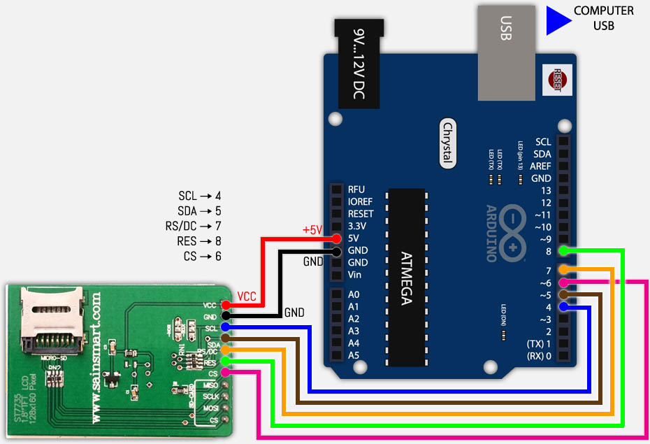
In this example we will use an Arduino Uno R3, but I’m confident it will work with other Arduino versions as well. The pin-out is for the SainSmart version of this display!
SainSmart 1.8″ Color Display Pins
Group
Pin
Purpose
Backlight
VCC
+3.3 … 5 Volt
GND
Ground
Display
SCL
Display Clock
SDA
LCD Data (SPI)
RS/DC
Mode: Command/Data
RES
Controller Reset
CS (TFT)
Chip Select for display
SD-Card
MISO
Master In Slave Out (SPI)
SCLK
Clock (SPI)
MOSI
Master Out Slave In (SPI)
CS (SD)
Chip Select for SD-Card
If you’re like me, then you might be able to guess the purpose of the pins, but you might not be quite sure yet what to do with them.
Basically, besides the obvious backlight, we tell the controller first what we are talking to with the CS pins. CS(TFT) selects data to be for the Display, and CS(SD) to set data for the SD-Card. Data is written to the selected device through SDA (display) or MOSI (SD-Card). Data is read from the SD-Card through MISO.
MOSI = Master Out Slave In, or in other words: The Master (Arduino) sends data out to the Slave (Display). MISO = Master In Slave Out, or the Slave (Display) sends data out to the Master (Arduino).
Both, for exchanging data and commands, of course need a clock for proper timing: SCL for the Display, and SCLK for the SD-Card.
For the display we need additionally the ability to toggle between sending data (text, drawings, etc) and sending command (clear screen, etc).
And we need a reset option for the display as well of course.
Adafruit vs SainSmart pins
When comparing the Adafruit display with the SainSmart display, you’ll notice that the AdaFruit display has less pins, as they combined some pins:
SainSmart pins SDA (Display Data) and MOSI (Data to SD-Card) are combined to Adafruit pin MOSI
SainSmart pins SCL (Display Clock) and SCLK (SD-Card clock) are combined to Adafruit pin SCK
So when using both display and SD-Card, and utilizing the Adafruit libraries with a SainSmart display, you will need to connect SDA to MOSI, and SCL to SCLK.
Note that this does make sense, since the controller often works either in Display or SD-Card mode (through the chip select pins).
Group: Backlight
Well, I guess those are pretty obvious – connect them and your display has a backlight. Vcc goes to +5 Volt (it’s actually 3.3 to 5V) and GND goes to ground.
Group: Display
As mentioned before, the display has a SLOW and a FAST mode, each serving it’s own purpose. Do some experiments with both speeds to determine which one works for your application. Of course, the need of particular Arduino pins plays a role in this decision as well …
Note : In either case, backlight is desired of course. Note : The selected pins depend on the definitions in your Arduino sketch and on the type of pins needed (PWM vs SPI).
Note: Adafruit displays can have different colored tabs on the transparent label on your display. You might need to adapt your code if your display shows a little odd shift. I noticed that my SainSmart display (gree tab) behaves best with the code for the black tab – try them out to see which one works best for yours.
Here is a little video demonstrating the Low Speed and High Speed speed difference (based on the awesome Adafruit Library and Demo’s):
Low Display Speed:
High Display Speed:
Low Speed Display
Low Speed display is about 1/5 of the speed of High Speed display, which makes it only suitable for particular purposes, but at least the SPI pins of the Arduino are available.
For this purpose the PWM pins are being used as displayed in the table below.
Pay attention to the order of the pins! (pin 6 is the last one in the list!)
Display Pins – Low Speed Display
SainSmart PIN
AdaFruit PIN
Arduino Pin
Purpose
SCL
SCK (SCLK)
4
Display Clock
SDA
MOSI
5
Display Data
RS/DC
D/C
7
Command or Data Mode
RES
RESET
8
Reset
CS (TFT)
TFT_CS
6
Chip Select (Display)
SainSmart 1.8″ TFT Arduino Display – LOW SPEED
After connecting the display in Low Speed configuration, you can load the first example from the Arduino Software (“File” “Example” “Adafruit_ST7735” – recommend starting with the “graphictest“).
Make sure to comment and un-comment the right parts and double check that the pin numbers in the defines match the pins you’re using.
Below the code parts for a LOW SPEED display (pay attention to the highlighted lines) – keep in mind that the names of the pins in the code are based on the Adafruit display:
// For the breakout, you can use any (4 or) 5 pins #define sclk 4 // SainSmart: SCL #define mosi 5 // SainSmart: SDA #define cs 6 // SainSmart: CS #define dc 7 // SainSmart: RS/DC #define rst 8 // SainSmart: RES
//Use these pins for the shield! //#define sclk 13 //#define mosi 11 //#define cs 10 //#define dc 9 //#define rst 8 // you can also connect this to the Arduino reset
// Option 1: use any pins but a little slower Adafruit_ST7735 tft = Adafruit_ST7735(cs, dc, mosi, sclk, rst);
// Option 2: must use the hardware SPI pins // (for UNO thats sclk = 13 and sid = 11) and pin 10 must be // an output. This is much faster - also required if you want // to use the microSD card (see the image drawing example) //Adafruit_ST7735 tft = Adafruit_ST7735(cs, dc, rst);
...
Compile and Upload the Sketch and you should see the first results on your new TFT screen.
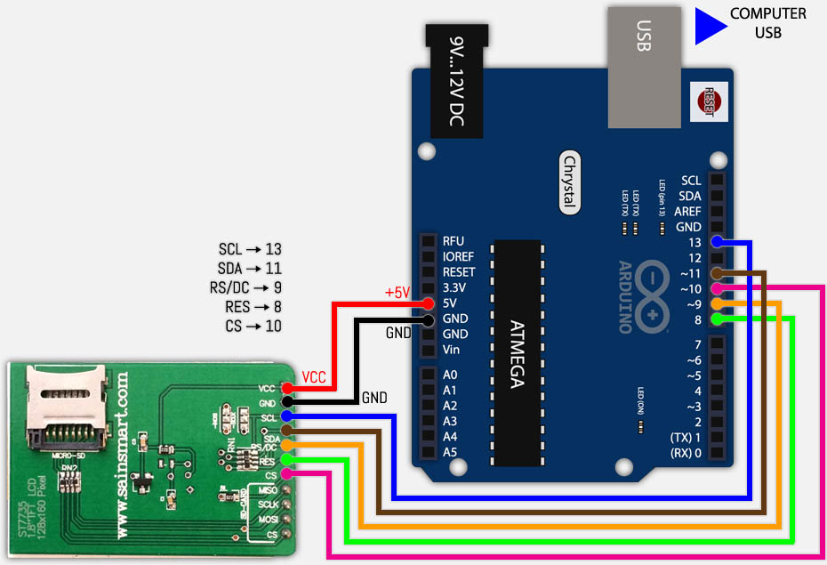
High Speed Display
High Speed is almost 5 times faster (according to Adafruit 4 – 8x faster) than Low Speed display and you’ll really notice the difference.
For High Speed display we will need to use the SPI pins of the Arduino – which can be a problem when you’d like to use these pics for other purposes.
Display Pins – High Speed Display
SainSmart PIN
AdaFruit PIN
Arduino Pin
Purpose
SCL
SCK (SCLK)
13
Display Clock
SDA
MOSI
11
Display Data
RS/DC
D/C
9
Command or Data Mode
RES
RESET
8
Reset
CS (TFT)
TFT_CS
10
Chip Select
SainSmart 1.8″ TFT Arduino Display – HIGH SPEED
As with the previous setup; we will need to make sure that the proper lines are marked as comments or code.
// For the breakout, you can use any (4 or) 5 pins //#define sclk 4 //#define mosi 5 //#define cs 6 //#define dc 7 //#define rst 8 // you can also connect this to the Arduino reset
//Use these pins for the shield! #define sclk 13 // SainSmart: SCL #define mosi 11 // SainSmart: SDA #define cs 10 // SainSmart: CS #define dc 9 // SainSmart: RS/DC #define rst 8 // SainSmart: RES
// Option 1: use any pins but a little slower //Adafruit_ST7735 tft = Adafruit_ST7735(cs, dc, mosi, sclk, rst);
// Option 2: must use the hardware SPI pins // (for UNO thats sclk = 13 and sid = 11) and pin 10 must be // an output. This is much faster - also required if you want // to use the microSD card (see the image drawing example) Adafruit_ST7735 tft = Adafruit_ST7735(cs, dc, rst);
...
Compile and upload, and you will notice that this demo goes a lot faster now.
Group: SD-Card
For working with the SD-Card we will need to do some additional wiring and the display wiring will be based on the Fast Display Mode.
as mentioned before: The used pins depends on the defined pins in the Sketch, but here we assume the presented pins.
Connecting Display and SD-Card
Note that SCLK is connected to SCL, and that MOSI is connected to SDA for the SainSmart variant of the 1.8″ TFT LCD Color Display.
Display Pins – High Speed Display and SD-Card
SainSmart PIN
AdaFruit PIN
Arduino Pin
Purpose
SCL
SCK (SCLK)
13
Display Clock
SDA
MOSI
11
Display Data
RS/DC
D/C
9
Command or Data Mode
RES
RESET
8
Reset
CS (TFT)
TFT_CS
10
Chip Select Display
MISO
MISO
12
SD Data (Read from SD)
SCLK
SCK (SLK)
(13)
SD-Card Clock
MOSI
MOSI
(11)
SD Data (Write to SD)
CS (SD)
CARD_CS
4
Chip Select SD-Card
SainSmart 1.8″ TFT Arduino Display – HIGH SPEED with SD-Card
Image on the SD-Card for the Demo’s
Before we can test this, we will need a 120×160 pixel BMP picture (24-bit) on an SD-Card.
The SD-Card needs to be FAT-16 or FAT-32 formatted, single partition, and the BMP file needs to be placed in the root (ie. not in a directory or anything like that).
You can name your BMP file “parrot.bmp” or modify the Sketch to have the proper filename (in “spitftbitmap” line 70, and in “soft_spitftbitmap” line 74).
Example: bmpDraw("mypicture.bmp",0,0); (in case you call your file “mypicture.bmp”).
Example BMP on a SainSmart Display w/Arduino
Demo’s
The demo “spitftbitmap” is the easiest to modify:
1 2 3 4 5 6 7 8 9 10 11 12 13 14 15 16 17
... // TFT display and SD card will share the hardware SPI interface. // Hardware SPI pins are specific to the Arduino board type and // cannot be remapped to alternate pins. For Arduino Uno, // Duemilanove, etc., pin 11 = MOSI, pin 12 = MISO, pin 13 = SCK. #define SD_CS 4 // Chip select line for SD card #define TFT_CS 10 // Chip select line for TFT display #define TFT_DC 9 // Data/command line for TFT #define TFT_RST 8 // Reset line for TFT (or connect to +5V)
//Use these pins for the shield! //#define TFT_CS 10 //#define TFT_DC 8 //#define TFT_RST 0 // you can also connect this to the Arduino reset
... // TFT display and SD card will share the hardware SPI interface. // Hardware SPI pins are specific to the Arduino board type and // cannot be remapped to alternate pins. For Arduino Uno, // Duemilanove, etc., pin 11 = MOSI, pin 12 = MISO, pin 13 = SCK. #define SPI_SCK 13 #define SPI_DI 12 #define SPI_DO 11
#define SD_CS 4 // Chip select line for SD card #define TFT_CS 10 // Chip select line for TFT display #define TFT_DC 9 // Data/command line for TFT #define TFT_RST 8 // Reset line for TFT (or connect to +5V)
//Use these pins for the shield! //#define TFT_CS 10 //#define TFT_DC 8 //#define TFT_RST 0 // you can also connect this to the Arduino reset
Now that we did our first tests, time to play around with some of the basic functions to display data on a display.
As you have seen before the Adafruit_GFX library (supported by the Adafruit_ST7735 library) makes this easy for us – More information can be found at the GFX Reference page.
Basic code template
Based on our High Speed Display example: The following basic steps are needed before we can work with the graphics display.
The first block is to define the pins (lines 4-8), next add the needed libraries with includes (lines 12-14).
After that we need to define the variable “tft” of the object type “Adafruit_ST7735” (line 18).
In the setup() function one would typically first blank the screen (line 22).
Your code then can either be placed in setup() for a one time run or in loop() for repeating the code over and over again.
tft.initR(INITR_BLACKTAB);// initialize a ST7735S chip, black tab // If your TFT's plastic wrap has a Red Tab, use the following: //tft.initR(INITR_REDTAB); // initialize a ST7735R chip, red tab // If your TFT's plastic wrap has a Green Tab, use the following: //tft.initR(INITR_GREENTAB); // initialize a ST7735R chip, green tab }
void loop(){
... // do your thing here
}
Basic Coordinate System of a Display
The display is build up out of pixels, which each can be addressed through a X,Y coordinate system.
Back in school the X went from left to right, and Y from bottom to top. This is not the case in this X,Y system.
X still goes from left to right, but Y goes from top to bottom as shown below – which is very common in displayes. Remember : Origin (0,0) is the UPPER LEFT CORNER.
X,Y Grid for a Display
Pixel Colors
Pixels in monochrome displays are easy: the pixels is either ON (1) or OFF (0).
With color displays this whole thing works a little bit more complicated as a color is build up out of 3 base colors: Red, Green and Blue.
Depending on your display this can be for example in 8 bit (256 colors), 16 bit (65,536 colors), 24 bit (16,777,216 colors), etc.
Our display (SainSmart or Adafruit) uses 16 bit colors.
Predefined colors:
The ST7735 library has some of the very basic colors predefined:
Calculating colors, for this screen can be done with the Color565 function of the ST7735 Library, which takes 3 parameters: Red, Green and Blue.
For Red and Blue only 5 bits are used, and for Green it’s 6 bits (don’t ask me why), but you don’t have to worry about that with this function.
1
2
3
4
5
...

Adafruit_ST7735 tft ....

...

color = tft.Color565(r,g,b)

...
Color565( red, green, blue);
This function calculates the 16-bit color code, based on the 3 values red, green and blue (all 3 are 8 bit numbers).
You can pass variables (int), or enter numbers straight.
However, when you enter the number here straight, use hexadecimal numbers, as with decimal numbers you will get unexpected results, for example:
Red: Color565( 0xFF, 0, 0)
Green: Color565( 0, 0xFF, 0)
I found the easiest way to pick a color is by looking at HTML Color codes, and for this purpose I’ve added one on this page.
Color picker:
Usage:
Click the input box and a popup will show a color picker. Choose your color, and the hex value will appear.
To use this in your Arduino Sketch: The first 2 characters represent RED, the second set of two characters is for GREEN and the last 2 characters represent BLUE. Add ‘0x’ in front of each of these hex values when using them (‘0x’ designates a hexadecimal value).
Example:
Thispurple is B700FE. The hex values are: red is B7, green is 00 and blue is FE.
Your Color565 call will be: Color565( 0xB7, 0x00, 0xFE );
Note : You can of course, use any application for color picking that shows hex values, or for example the color picker in Adobe Photoshop.
Graphics Functions
drawPixel( x, y, color );
Draws a single pixel at (x,y) in the indicated color.
drawLine( x0, y0, x1, y1, color );
Draw a line from (x0,y0) to (x1,y1) in the indicated color.
drawFastHLine( x, y, width, color );
Draws a horizontal line, starting at (x,y), of indicated width and color.
This function works faster for horizontal lines when compare to drawLine().
drawFastVLine( x, y, height, color );
Draws a vertical line, starting at (x,y), of indicated height and color.
This function works faster for vertical lines when compare to drawLine().
drawRect( x, y, width, height, color );
Draws an open rectangle, starting at (x,y) with a width, height, and a border line in the indicated color.
(x,y) indicates the upper left corner.
fillRect( x, y, width, height, color ); Draws a filled rectangle, starting at (x,y) with a width, height, in the indicated color. (x,y) indicates the upper left corner.
drawCircle( x, y, radius, color );
Draws an open circle at (x,y) with the indicated radius (in pixels) and a border in indicated color.
(x,y) indicates the center of the circle.
fillCircle( x, y, radius, color ); Draws a filled circle at (x,y) with indicated radius and filled with indicated color. (x,y) indicates the center of the circle.
drawTriangle( x0, y0, x1, y1, x2, y2, color ); Draws an open triangle, between the points (x0,y0), (x1,y1) and (x2,y2), with a border in the indicated color.
fillTriangle( x0, y0, x1, y1, x2, y2, color );
Draws a filled triangle, between the points (x0,y0), (x1,y1) and (x2,y2), in the indicated color.
drawRoundRect( x, y, width, height, radius, color );
Draws an open rectangle with rounded corners at (x,y) with indicated width and height and a border in the indicated color.
The radius indicates the radius of the individual corners.
(x,y) indicates the upper left corner of the rounded rectangle.
If radius times 2 is greater than the width or height: be prepared to see some unexpected effects.
fillRoundRect( x, y, width, height, radius, color );
Draws a filled rectangle with rounded corners at (x,y) with indicated width and height in the indicated color.
The radius indicates the radius of the individual corners.
(x,y) indicates the upper left corner of the rounded rectangle.
If radius times 2 is greater than the width or height: be prepared to see some unexpected effects.
drawBitmap( x, y, *bitmap, width, height, color );
This function can draw a single color bitmap (not to be confused with a BMP file).
For this you’ll need to define the constant “bitmap”.
The use of this function is a little beyond the scope of this article, but I just wanted to show that there is more depth to these libraries.
The bitmap upper left corner is (x,y), presumed to have a width and height as indicated, and will be drawn in the indicated color.
Text Functions
drawChar( x, y, character, color, backgroundcolor, fontsize ); Draws a character at a given location (x,y), where (x,y) represents the upper left corner of the character.
setCursor( x, y );
Positions the text “cursor” at the given location. This is where the text output continues when using print() or println().
print( text ); println( text );
Prints the given text string at the current cursor position. The println() variant will add a carriage return, so that the next text output starts on a new line.
setTextColor( color );
This sets the font color. Everything printed AFTER this statement will appear in the indicated color.
setTextColor( color, backgroundcolor );
This sets the font background color. Everything printed AFTER this statement will appear with the indicated background color.
setTextSize( fontsize );
With this statement, you can set the font size for tekst out put AFTER this statement. Typically fontsize values are 1,2,3,4,5,6,7,8,9,10, etc.
See the demo below for an example output. The size is an arbitrary number and does not match for example pixel height or anything like that.
setTextWrap( boolean );
Enable (true) or disable (false) word wrapping at the end of a line and will only affect text output AFTER this statement.
Screen Functions
setRotation( rotation );
This function is used to indicate what corner of your display is considered (0,0), which in essence rotates the coordinate system 0, 90, 180 or 270 degrees.
The SainSmart display uses (0,0) as the upper left corner when the display is standing up right (i.e. pins in a breadboard for example).
However, if your application needs your screen sideways, then you’d want to rotate the screen 90 degrees, effectively changing the display from a 128×160 pixel (WxH) screen to a 160×128 pixel display. Valid values are: 0 (0 degrees), 1 (90 degrees), 2 (180 degrees) and 3 (270 degrees).
fillScreen( color ); Fills the entire screen with a give color, ideal for example for blanking the screen by setting the color to black.
invertDisplay( boolean );
Sets the screen to inverted (true) or normal (false);
Display Demo
Based on these functions, I did create a little demo to show what these functions do. Either download the file or just copy the code and paste it into an empty Arduino Sketch.
void setup(){ // Init serial for serial monitor, so we can see debug text in the Serial Monitor Window
Serial.begin(9600);
Serial.println("Display Function Tests Started");
// If your TFT's plastic wrap has a Black Tab, use the following:
tft.initR(INITR_BLACKTAB);// initialize a ST7735S chip, black tab // If your TFT's plastic wrap has a Red Tab, use the following: //tft.initR(INITR_REDTAB); // initialize a ST7735R chip, red tab // If your TFT's plastic wrap has a Green Tab, use the following: //tft.initR(INITR_GREENTAB); // initialize a ST7735R chip, green tab
Serial.println("setup() - Init Completed"); }
// Draw some lines
Serial.println("Draw some lines");
tft.drawLine(10,10,100,100,ST7735_WHITE);
tft.drawLine(100,100,10,50,ST7735_GREEN);
tft.drawLine(10,50,100,50,ST7735_RED);
tft.drawLine(100,50,10,10,ST7735_YELLOW);
delay(3000);
// Draw some rectangles
Serial.println("Draw some rectangles, with delay between open and filled rectangle");
tft.drawRect(20,20,100,100,ST7735_RED);
tft.drawRect(40,10,10,100,ST7735_YELLOW);
delay(2000);
tft.fillRect(50,10,50,20,ST7735_RED);
tft.fillRect(80,80,10,10,ST7735_YELLOW);
delay(3000);
// Clear screen
Serial.println("Fill screen with BLACK");
tft.fillScreen(ST7735_BLACK);
// Draw some circles
Serial.println("Draw some circles, with delay between open and filled cicle");
tft.drawCircle(70,70,10,ST7735_WHITE);
tft.drawCircle(70,70,50,ST7735_RED);
delay(2000);
tft.fillCircle(20,20,50,ST7735_YELLOW);
tft.fillCircle(20,20,10,ST7735_BLUE);
delay(3000);
// Draw some triangles
Serial.println("Draw some triangles, with delay between open and filled triangles");
tft.drawTriangle(64,100,64,150,100,150, ST7735_YELLOW);
tft.drawTriangle(64,100,44,150,84,150, ST7735_RED);
delay(1000);
tft.fillTriangle(64,100,64,150,100,150, ST7735_YELLOW);
tft.fillTriangle(64,100,44,150,84,150, ST7735_RED);
delay(3000);
// Clear screen
Serial.println("Fill screen with BLACK");
tft.fillScreen(ST7735_BLACK);
// Draw rectangles with rounded corners for a dialog // Big box
Serial.println("Display panic message!");
tft.fillRoundRect(14,16,100,100,8, tft.Color565(0xC4,0xC4,0xC4));
tft.drawRoundRect(14,16,100,100,8, tft.Color565(0x99,0x99,0x99)); // Title
tft.fillRoundRect(20,8,60,20,4, tft.Color565(0xFF,0,0));
tft.drawRoundRect(20,8,60,20,4, tft.Color565(0x99,0x99,0x99)); // Title text
tft.setCursor(28,14);
tft.setTextColor(ST7735_WHITE);
tft.print("WARNING"); // Message
tft.setTextColor(ST7735_RED);
tft.setCursor(22,38);
tft.print("Something is");
tft.setCursor(22,48);
tft.print("very wrong!");
tft.setCursor(22,68);
tft.print("OMG - PANIC !");
tft.setCursor(22,88);
tft.print("We're out of");
tft.setCursor(22,98);
tft.print("COFFEE!!!");
delay(3000);
// Clear screen
Serial.println("Fill screen with BLACK");
tft.fillScreen(ST7735_BLACK);
// Write a long text with word wrap
tft.setTextColor(ST7735_WHITE);
tft.setCursor(0,0);
tft.print("Lorem ipsum dolor sit amet, consectetur adipiscing elit. Curabitur adipiscing ante sed nibh tincidunt feugiat. Maecenas enim massa, fringilla sed malesuada et, malesuada sit amet turpis. Sed porttitor neque ut ante pretium vitae malesuada nunc bibendum. Nullam aliquet ultrices massa eu hendrerit. Ut sed nisi lorem. In vestibulum purus a tortor imperdiet posuere. ");
delay(2000);
// Clear screen
Serial.println("Fill screen with BLACK");
tft.fillScreen(ST7735_BLACK);
Serial.println("Test font sizes");
tft.setTextWrap(true);
tft.setTextColor(ST7735_WHITE);
tft.setCursor(0,0);
delay(1000);
In the demo and the text, not all functions have been explained or demoed.
Functions like the use of bitmaps and custom fonts is something I haven’t done much with (yet), but might certainly be worth exploring.
Support Us ...
Your support is very much appreciated, and can be as easy as sharing a link to my website with others, or on social media.
Support can also be done by sponsoring me, and even that can be free (e.g. shop at Amazon). Any funds received from your support will be used for web-hosting expenses, project hardware and software, coffee, etc.
Thank you very much for those that have shown support already! It's truly amazing to see that folks like my articles and small applications.
Please note that clicking affiliate links, like the ones from Amazon, may result in a small commission for us - which we highly appreciate as well.
Please consider disabling your ad blocker for our website. We rely on these ads to be able to run our website. You can of course support us in other ways (see Support Us on the left).
Please consider disabling your ad blocker for our website. We rely on these ads to be able to run our website. You can of course support us in other ways (see Support Us on the left).
There are 130 comments. You can read them below. You can post your own comments by using the form below, or reply to existing comments by using the "Reply" button.
Thanks so much for your tutorial! I just don’t understand the SD Card wiring. How can I connect SCLK to SCL and MOSI to SDA on my Sainsmart TFT LCD? I was using male-female wires in all my wiring but I just don’t know how to wire those two things. Please reply!
I would love to help out, but I’m not sure what the problem is that you’re running into.
If I understand you correctly, you’re not having the right wires? I used a breadboard for the experiment, which gives me the option to connect multiple wires to one pin.
Another trick, if you’re not using a breadboard and your wire ends allow this, is by sticking a wire in the back of the wire that’s already there – it’s not perfect and like I said, it depends on the ends of your jumper wires, mine allow this (although it most certainly was not made for that).
For a final setup, you could split a wire and solder it together with another wire.
I apologize if I didn’t understand you question correctly.
I apologize for not being specific in my issue. I’m a beginner in these things but I’ll try detailing it as well as possible.
In your tutorial, I connected each part of my LCD to the Arduino exactly as you said. However, I wasn’t using a breadboard so I wasn’t able to connect multiple wires to one pin as you did. This is why I didn’t (and still don’t) know what to do when you mention that SCLK should be connected to SCL (which is then connected to pin 13) and MOSI to SDA (which is then connected to pin 11) on my LCD. I understood that SCL is connected to pin 13 and that SDA is connected to pin 11 but how can I connect SCLK to SCL and MOSI to SDA? Basically, How can I connect a pin on my LCD to another pin on the same LCD without using a breadboard?
PS: If I am to use a breadboard just to connect SCLK to pin 13 and MOSI to pin 11, is it still possible to have my LCD not fixed to the breadboard? If it is possible, then how do I do so?
Sometimes it can be difficult to explain in text what you’re looking at …
So you’re wondering how to connect 2 connectors to one pin (basically), right?
I guess it depends on the materials you have available,… breadboard (for experimenting) works easiest, but for a “final” product it’s obviously not a good solution. For a final product I’d actually make a suitable cable for that, with 3 ends. One end to the Arduino, and the other 2 ends to each of the LCD pins.
If you’re just using jumper wires, then you could cut two of them in 2 pieces. I’d say, one cut in the middle, strip the wires at the ends you cut and twist them together. Grab the 2nd jumper wire and cut it as close as possible to the pin you don’t need or want to use. Strip the wire again and twist it with the previous cable you made. This way you might be able to still use it in other future projects. (hope that made sense)
You could also consider using a Multiway Screw terminal (a.k.a. “kroonsteen” in Dutch) and bind the pins together there (link for a picture), or you could consider using test cable with crocodile clip (picture).
Do you know if you can use the Arduino TFT library with the SainSmart 1.8 TFT ? After reading the Arduino website, it sounds likes the Arduino library adds things to the GFX and ST3775 library that may not work with the SainSmart TFT…..
well i always have a error on all the sketches and it says adafruit st7735 does not name a type. is is my arduino version 1.0.5 or the codes are outdated help please i never got my screen to work because of that one error help:(
Thank you for this tutorial. But I could use some help. I want to have the LCD sideways and in the center of the screen have text scrolling across the screen. I need the text to be set in one line not spaced out like this.
Sounds like you need to use the “setRotation” function first, so text is displayed sideways.
With functions like “setCursor(x, y);” you can position the text, and “print(“Something”);” and allow you to print the text at indicated position.
“setTextSize” allows you to change font size, but you could also explore the option to upload your oen font/font size.
As for scrolling, you’ll have to play a little with the other functions available in the library. I haven’t done any testing lately, but you could draw the text, draw a black rectangle, reposition the cursor, draw text, etc. (for some of the functions, see the chapter “Some Basic Graphics Functions” above)
I hope this helps you get started – unfortunately, I’m not anywhere near my equipment (traveling) to do some of these tests for you.
Jan 20, 2015 - 11:03 AM - Daniel Gordon Comment Link
Hello,
I am having issues with getting the high speed code to work. The low speed works just fine but as soon as I modify the pins listing and comment/uncomment the two lines of code the display just stays white.
If you modified the code and changed the physical pins, then the high speed code should work just fine. I’m assuming you’re using the exactly same display?
I am using the following components for my project :SainSmart MEGA2560 R3, SainSmart 7″ TFT LCD Display, SainSmart TFT LCD Adjustable Shield. I wanted to get the .bmp file image on the lcd screen to create some user interface. So which libraries should i use in order to suceed in my task.
PS: I tried Arduino TFT library, but I think it is not compatible to this display kind.
Did you mean this one (found at Amazon)? They state that they “will provided you the whole document including the example project of the kit“.
At Amazon they provide a link to a downloadable zip file for this setup. The ZIP file has a folder in it called “CTE_MEGA_shield” which seems to address how to connect it to the Arduino.
In the end, I’m not quite sure what setup you’re using, do you have a link?
At the SainSmart website they also offer an email address for support: support@sainsmart.com. Maybe you can contact them?
Sainsmart is worst in technical support, won’t reply any of our mails, regretting buying their product.
Currently I have UTFT and UTFT_touch libraries, but there’s no example in it to try how to get the image from SD card on to the screen. So please assist.
Under the firectory “UTFT_DUE” I do see some files suggesting the ability to display a PICture. I also found the developers website of this library: http://www.henningkarlsen.com/electronics/
Examples like button test, calibration , Quickdraw, etc., with respect to those libraries are working fine. But there is no example on image fetch from SD. So I am not sure which libraries I should go with.
that sounds like we might have a typo or wrong path for the picture file? From your filename I assume it’s placed in root, and saved as you described (allcaps)?
I also noticed that you will need to convert a picture first, but by the filename you’re using, you have indeed done this.
In the documentation, it also states: “Requires that you #include <avr/pgmspace.h> when using an Arduino other than the Due” (Page 8 of the reference manual).
Obviously just for testing, and if you use only one picture then you might want to remove the loop, or even move this to the “setup()” section (since it might be needed only once).
thank you very very much for your efforts to provide this perfect tutorial! For a (still secret ;-) project I build up your configuration and it works perfectly! I want to file my project also in an tutorial and therefore I ask you kindly, if you could provide me your fritzing library for the Display?
many thanks in advance an go ahead with further perfect tutorials!
As for the libraries: In the green boxes above you’ll find the files, but I’m not the copyright holder of those files. You’d have to contact the creators through their website (AdaFruit). Since they are on Github, I assume you’re free to use them, just keep the Copyright statements in tact.
As for my own code: feel free to use it, and if relevant please leave the copyright notice …
Thank you very much for the polite way of asking, most people do not take the effort … and will you let us know when the secret project becomes public? I’m really curious now …
thank you very much for your quick response. Sorry, my request was not clear enough described (I didn’t mean the arduino/adfruit libraries for the Arduino IDE): I want to file my project with nice self explaining pictures like your tutorial here. Therefor I asume you used also fritzing to make pictures like fig4. right? These files are a type *.fzz if I know this right. Up to now I couldn’t find a fritzing library for the Display. Hopefully I’m not to stupid but up to now I could find this in the standard fritzing library.
Dorry for not right away understand what you’re asking, … I was not familiar with Fritzing (thanks for the tip though!).
I actually did draw these figures with PhotoShop … Based on a drawing I once made of the Arduino Uno I (and re-using it in each drawing).
Looking at the Fritzing website, it seems that there should be an Arduino component though, but the display might be a problem, but I have yet to test it.
I also have seen quite a few folks working with so called Arduino Simulators/Emulators, AutoDesk (it’s free as far as I can see) allows you to make electronic designs as well with 123D Circuits and allows you to download the image as well. Not sure if they have the display available though either ….
ah fine – this explains a lot. Thanks for information to the other simulators, I will have a look at them. If I will succseed with fritzing I will let you know.
So, after a few hours of challenging searching through many many web sites I finally was able to create my first, own fritzing part – the Display we talked about here in this thread:
I created a *.svg-file with “Sketsa SVG Editor” and created a new part in fritzing – it works !
This took my just 20 Minutes, so I think, the work is useful.
I already tried to start with an tutorial – which obviously will be bloddy primitive, but it might help somebody to turn on the right street…
If there out is none with better proposal I will share this tutorial in short time on an appropriate forum.
How to say that… Maybe the direct way : I am very interested in saving 20 minutes, if you could share your fritzing file, it would be super-great from you…
Please feel free to share it in the Arduino forum here … I’m sure others will benefit from it in the future. Thank you very much for the hard work and for sharing!
I’m using this saindsmart tft together with an Adafruit Data logger shield. I can make the tft work and print some stuff, and previously also the data logging worked fine… When i tried to show the data on the screen though, by adding some code from and example i found using the same tft, i noticed that the data logging shield can’t write on the SD card anymore.
Allthought i’m not using the SD capabilities of the tft and haven’t wired those, and I have wired all pins like you showed in the ‘slow’ mode…
I’m guessing there must be some kind of conflict with the SD cards but i can’t imagine where…
First thing that comes to mind is a conflict in used libraries maybe? Even if you’re not using the SD card functionality, maybe something in one of the libraries is still “talking” to the pins and therefor conflicting with another library?
I’m just guessing here, since I do not know all the details of your setup. But most often I found that to be the cause of such unexpected issues.
I do not have the AdaFruit Data Logger Shield, and at first glance I see RT Clock and space to solder as an advantage, but not much more than that (please correct me if there are mote advantages). Can you run your experiments without the data logger? Just to see if everything works fine anyway. After all, the TFT has an SD card available.
I was thinking the same, some conflict in libraries; because everything seems to be working just fine untill I put them to work together. I tried taking out pieces of code of the data logging to see if it would show the sensor readings without writing them to an SD card and noticed that everything suddenly worked when i removed this, and only this, piece of code:
if (! logfile) { error(“couldnt create file”); }
This piece of code always worked before, without using the tft, so i’m guessing it’s this piece of code that made the conflict happen.
After changing this, It stopped giving that error and for some reason, writing on the SD card still works without a problem…
In other words, everything is working fine now, but i have no idea whatsoever why that is. :) (and it’d be quite educational to know what the problem could be since i’m just a beginner in the whole arduino story..)
Cause i’m just a beginner, I don’t really know much about what is what yet exactly :) As far as i’m concerned, i think it’s the file created to write on (a .csv file), a bit like writing on a tft or lcd.
Don’t worry Jan – I’m not the biggest expert either …
I see that “logfile” is a “File” handle (code: File logfile;), and created in this section:
  // create a new file
  char filename[] = "LOGGER00.CSV";
  for (uint8_t i = 0; i < 100; i++) {
    filename[6] = i/10 + '0';
    filename[7] = i%10 + '0';
    if (! SD.exists(filename)) {
      // only open a new file if it doesn't exist
      logfile = SD.open(filename, FILE_WRITE);
      break;  // leave the loop!
    }
  }
It will NOT overwrite a file … so if you have 99 files (LOGGER01.CSV … LOGGER99.CSV), the program will fail. This is where this part of the code comes in:
  if (! logfile) {
    error("couldnt create file");
  }
As I understand, such a file is created each time you start the Arduino – so boot the Arduino 99 times and you’re done … not sure why that second part would break things though.
Two questions: I cannot manage to get the display into sleep mode with the DISP_OFF flag. How do I do it? Also, is it possible to deactivate the backlight by software command?
Unfortunately, I’m traveling at the moment and am nowhere near my stuff to try what might work and what not. I’m pretty sure though there is a way to get the backlight to go off – or maybe better put: get the display to go to sleep.
When looking at the library code, around line 152, I’ve noticed quite a few commands that could possible do this (sleep mode, power control). I also read somewhere that the display automatically enters a sleep mode after a soft reset. The spec-sheet of the ST7735R suggests there is the display off option (as you mentioned) and a “sleep IN” mode as well (page 80) – but like I said; I do not have access to my Arduino w/Sainsmart display at the moment to test any of this …
I edited the Adafruit_ST7735.h library to get the possibility of activating the sleep mode by command. I changed the part where the “writecommand” can be found from private to public
In that way I can use “writecommand(SLPIN);” and “writecommand(DISP_OFF);”.
However, by using that, the display goes white and the LED backlight remains switched on. No content is shown anymore. But having the display in a bright white even with backlight is not the sleep mode or display off mode that I would expect .
It seems that the LED backlight is powered by a regulator or another circuit on board, since there is no backlight pin as in the Adafruit version of the screen.
I will try to get more familiar with the libraries and that stuff.
Interesting find – I’d expect that “sleep” would mean “backlight OFF” as well … if not, then this would be a rather useless function …
I wish I could access my stuff right now to test along,… please let us know if you find out a trick that might do it right. I’d be very interested in that as well – specially when I decide to use the display in a more permanent setting.
Maybe add a switch that we can control with software, although I’d hate to have to add this extra “hardware” to get a basic function to work.
I guess it is just “the wrong display” (https://github.com/notro/fbtft/wiki/LCD-Modules#sainsmart-18). It seems that the sainsmart version doesn’t allow to control the backlight. Since I use this display in a remote sleep phase scanner that I am programming, it drained the LiPo battery (1000mAh) during the night. My circuit draws up to 90 mA only due to the backlight. So, this is not the display that I need. I have already ordered the adafruit version where backlight can be controlled.
That’s good to know … well, not really good, but at least something to take into account when choosing this display.
To wake the display up, I assume you’d use a button of some sorts. Maybe with small effort, the +5V (Vcc) can be “switched”, my initial thought was a small relay, but I’m sure there is a good way to do this in solid state. I’d have to toy around with that to find the proper way to do this.
Exactly, the display should be in sleep mode mostly all the time. Only when user input is made, the display shall wake up and display data.
Well, if I cut VCC to the sainsmart version, the µSD slot cannot be used anymore. Since I also need the data store, this isn’t the solution for me. :(.
I will give a comment about the backlight function as soon as the adafruit version is there.
Thank you for creating this website, been very helpful.
I have a problem when using my Arduino UNO with a generic Ebay 128×160 TFT display & SD card. I’m using it in the high-speed configuration. Both devices work well individually, but whenever the SD card is written to, the display will glitch. The display’s data is never lost (I don’t have to re-write over glitch data). I amusing the Arduino .h files and the chip selects are separate. It appears that the display does not like to have data on the SPI buss that does not belong to the display. I have also verified with a scope that the chip select lines are not being activated simultaneously.
I have ran into situations before with SPI pin issues … specially when “one” device (TFT+SD) use the same pin. However, with the proper switching I did get it to work just fine on the Sainsmart.
Does the seller of your display offer any libraries/code/documentation?
Hi Hans, sorry for the late reply. I did figure out that the line of code which opens the SD card for writing is what has been causing the display to refresh and blink. I checked the enable lines for the display and SD card with a scope and there is never a time when they are both enabled simultaneously. So I “fixed” the problem by minimizing the number of instances where I open the SD card for writing.
You obviously gave excellent examples. I’ve only just started playing with arduino and I got the ‘slow’ screen version working second time around (first time it tried to go to wrong comm port, so I unplugged arduino board and restarted the IDE and it worked just fine). OH, and I used a Nano instead of an UNO and still it worked. Thank you. Now I just have to figure out how to write text on the screen only (temp and humidity) and log the temp/humidity/date/time data to a micro sd card and I’m set. Thank you.
Great to hear that you’re having fun with this little project, and all that with a Nano – very cool!
As you can see in the demo, pushing Text to the screen is not that complicated either;
  tft.setCursor(0, 0);
  tft.setTextSize(1);
  tft.println("Some text you'd like to display");
To format things nice, you might have to juggle the coordinates (setCursor) and play a bit with that, but I guess that’s also part of the fun. Above you’ll find a list with Text functions as well, like setting color and such.
This is a really helpful tutorial, thanks for making it! I’m having an issue with initiating the graphicstest from the Adafruit_ST7735 library using the high speed display set-up. When I use the code you provided, nothing shows up on my screen, but when I change it so that I use option 1, the graphicstest runs fine. What’s wrong with option 2?
Yes, the wiring is correct. At the moment, I have the wiring set up to also connect the SD card, but I don’t think that’s where the issue is coming from. Any other ideas?
I’m using the same SainSmart display you used in this tutorial. I’m not sure if this affects anything, but the Arduino board I’m using is Mega and I’m doing my wiring over a GPS shield (I’m using the GPS for another part of my project). I’m pretty new to working with Arduino, so sorry if I’m sounding really clueless.
Don’t say sorry – I’m not an expert either and I have been a newby too …
I have not tried the MEGA yet, but I do know there are some differences (like some pins) that you have to take in consideration. The GPS shield might interfere as well. I’d start with as little components as possible so you can break down where the issue occurs.
So I switched my Mega board for an Uno and now everything runs perfectly! Thank you so much for your help and patience with me, I really appreciate it!
I’m sure you will get it to work with the MEGA, just have to figure out which pins to use and see if the library defines those same pins as well – just in case you’d like to figure this out in the future.
First thing I’d check is the wiring, I’d assume you’d use the wiring as suggested here, but I had to ask, since some folks mix the wiring for fast and slow refresh …
I am new in this so I have no experience. Actually I am trying to create a good interface with the spark core and the HX8357 touchscreen to control a treadmill. I want to get access to the SD card images to make them the icons of my application.
The problem is that I can’t get the access to the SD card and I don’t know why this is happening. I tried several connections between the core and the touchscreen but it doesn’t work. I took care of both CS pins separately but it seams that I am blocked with this. I think I can only get access to the touchscreen and not to the SD card. I don’t know what else to do. Can somebody help me please?
I have no experience with the Spark One (I’m assuming it this one), maybe one of the other readers is more familiar with it.
What I do see is that it’s Arduino compatible, yet uses an ARM processor instead of a microcontroller like the Arduino does. So I’m not 100% sure if it emulates parts or not, and how compatible it really is. Maybe the CS pin implementation isn’t as compatible as they claim (I wouldn’t know to be honest).
The Spark One looks like a fun thing to play with though … is there a way to contact the developers?
Do you have any tutorials for this module with the shield on? Im wondering what changes in code if the tft has the shield on it? How should I access the individual SDA/SCL pins etc?
Considering both your questions: I’d look and see if the pins are properly defined in the sketch for controlling the display. Unfortunately I do not have a shield version available – would be easier if manufacturers started donating stuff ….
If you used a shield version from AdaFruit, and you’ve actually purchased it there, then consider contacting them as well.
As for finding the right pins, some shield print it on the PCB which pin is what, so you can find to what Arduino pin they are connected. Cheaper shield versions might not have this printed on the PCB which makes it a lot more difficult. See for example figure 1.
If SD works fine, but display not, then I’d definitely look at the CS (Chip Select) pin. I assume that power is OK.
No, define’s need to remain commented as those are not actual “code” but more so compiler directives.
What it in essence does, is (TFT_CS as example) tell the compiler to replace every occurrence of “TFT_CS” with the number “10”.
In the code you’ve linked to, this is represented a little confusing.
#define TFT_CS     10
#define TFT_RST    9  // you can also connect this to the Arduino reset
                      // in which case, set this #define pin to 0!
#define TFT_DC     8

// Option 1 (recommended): must use the hardware SPI pins
// (for UNO thats sclk = 13 and sid = 11) and pin 10 must be
// an output. This is much faster - also required if you want
// to use the microSD card (see the image drawing example)
Adafruit_ST7735 tft = Adafruit_ST7735(TFT_CS,  TFT_DC, TFT_RST);

// Option 2: use any pins but a little slower!
#define TFT_SCLK 13   // set these to be whatever pins you like!
#define TFT_MOSI 11   // set these to be whatever pins you like!
//Adafruit_ST7735 tft = Adafruit_ST7735(TFT_CS, TFT_DC, TFT_MOSI, TFT_SCLK, TFT_RST);
You might need to update the numbers like I did in my sketch (match numbers with what your shield is doing). I’ve matched the comments of my code with the option numbers of the code you linked to. Obviously you can use only one set with defines.
// Option 2 (slow):
#define sclk 4  // Your example code: TFT_SCLK
#define mosi 5  // TFT_MOSI
#define cs   6  // TFT_CS
#define dc   7  // TFT_DC
#define rst  8  // TFT_RST

// Option 1 (fast):
#define sclk 13  // SainSmart: SCL,  Your example: TFT_SCLK
#define mosi 11  // SainSmart: SDA,  Your example: TFT_MOSI
#define cs   10  // SainSmart: CS,   Your example: TFT_CS
#define dc   9   // SainSmart: RS/DC,Your example: TFT_DC
#define rst  8   // SainSmart: RES,  Your example: TFT_RST
I know this is a little confusing, hope it helped you in the right direction – again: make sure the numbers match the pins on your Arduino.
I’m trying to figure out if there’s a “software” way to control backlight intensity on this particular model (without dedicated Ledpin we could PWM)
I’ve scouted the ST7735 data sheet and Adafruit_ST7735 library. It seems backlight is not ST’s business.
Besides VCC has a little impact on backlight intensity (3.3v … 5v), it’s far from enough… and I didn’t even tried to PWM on Vcc / Gnd, that would probably give weird results.
That is an interesting challenge for sure,… I honestly have never worked with the backlight dimming, and the “PWM” method might be the only solution to this – if it even works. I had to do some reading to catch up (haven’t worked in quite a while with this display) and this is all I could find.
I did read quite a few posts on the Arduino Forum, but the PWM method I have yet to test (see this Arduino link). I suspect this would be the only method that might work.
Thanks a lot for the guide – this is great! I have a slight problem with colors – White and Black show up properly, but when I try to use Red, for example, it gives me a Blue color instead. Green and Yellow are mixed up, Cyan is not Cyan, it’s strange because I’m using the standard color codes but I have to invert them somehow to make them work. It seems to me that my codes are not RGBB but BGRR or something like that.
As for the colors being BGR vs RGB; I have no clue, but I have seen these kind of “jokes” with LED strips as well. You might want to check the library.
I would guess the model you’re using is not the same model as the one I have used here. The function Adafruit_ST7735 might exist for your model as well – the hard part will be finding what model exactly you have.
So i read through a few comments but I am wondering how can you rotate the screen. For example the Fontsize part as well as the warning sign is read going downwards long ways but I would like to have it read going downwards short ways. So I would basically like to rotate the screen 90degrees.
Did you try at the function (in the beginning of your code):
setRotation( rotation );
This function is used to indicate what corner of your display is considered (0,0), which in essence rotates the coordinate system 0, 90, 180 or 270 degrees.
The SainSmart display uses (0,0) as the upper left corner when the display is standing up right (i.e. pins in a breadboard for example).
However, if your application needs your screen sideways, then you’d want to rotate the screen 90 degrees, effectively changing the display from a 128×160 pixel (WxH) screen to a 160×128 pixel display. Valid values are:
[…] Die Pinbelegung ist auf den Glupsch adapder abgestimmt. Alternativ kann auf einem kleinen Breadboard irgendein SPI Display gekoppelt werden z.B dieses. […]
Thank you for the compliment and even more for taking the time to post the settings/connections that worked for your Arduino Mega. It’s very much appreciated!
I have the 1.8″ TFT connected to an Arduino Mega 2560 and doing image loads from the microSD card, in large part because of this post, so thanks OQMty!
My connections:
Vcc/GND: As expected SCL (LCD) & SCLK (SD) -> Mega pin 51 SDA (LCD) & MOSI (SD) -> Mega pin 52 RS/DC -> Mega pin 46 RES -> Mega pin 47 CS (LCD) -> Mega pin 49 CS (SD) -> Mega pin 48
tft.initR(INITR_BLACKTAB); // initialize a ST7735S chip, black tab tft.setRotation(1); // Set rotation to place top-right corner near pins (pins to right of display)
It loads a 160×128 24-bit BMP from the SD card and draws it to the screen in around a second (mid-1,000-ms range). I have a fair bit of noise and distortion during the draw operation, which I suspect stems from the use of a rats’ nest of unshielded breadboard wires, but once the operation is finished the imagery is crisp and clear.
(Aside: My TFT had a green tab on the screen protector but only works when I use INITR_BLACKTAB to initialize the display.)
Thank you so much for this tutorial! After some tweaking and re-reading I got my display to spring to life!
There are a couple of strange things though:
When using a .bmp from the SD card, I have to use the tft.initR(INITR_REDTAB) function instead of the black or green. With the black one, it skews the colors horribly. In fact, it seems that with every test file I have to use a different tft.init. Also, the display doesn’t seem to be aligned right. There’s a border on the right side and bottom of whatever junk is left in the buffer, and text is chopped off at the top and left. Do you think I have a bad display or could this be a wiring fault?
in the graphicstest example file, there are initR’s for 144GREENTAB and BLACKTAB. The 144GREENTAB is what you use if you have the 1.44″ square display. However, the BLACKTAB was leaving the strange margin. I took a peek inside the .h file and saw lots of initR lines, and there was a line for 18GREENTAB or just GREENTAB So I tried that one and it works fine.
It’s also worth noting that my display is actually 128×160, NOT 120×160 as advertised. This means that any .bmp files I create have to be 128×160 to fill the screen. If your image doesn’t fill the screen the display just leaves whatever is in the frame buffer for that area, so whatever was running in the last sketch will be there.
I also noticed that there’s an include line for the GFX library nested inside the 7735 library, and my test files ran fine when I commented out my own include line. I’m taking this to mean that you don’t need to include the gfx library on its own.
I would definitely try that (omitting your own include). This was not the case when I wrote this article though, and I’m traveling so I do not have the chance to test this with my own gear.
Please let us know what your findings are … so I can add a warning near the source code above saying something like “if you see this, then remove the GFX include” …
Oh I don’t think including the gfx library in my sketch as well as it being referenced in the 7735 library was causing my screen margin error. I’m pretty sure that was caused by a combination of the screen actually being 128×160 and using the wrong initR.
For the record however, leaving the include in versus taking it out doesn’t seem to impact the compiled size of the sketch, so I wouldn’t worry too much about redundant libraries.
Thanks Mike for getting back with your findings. Yes, I would assume the compiler/linker would be smart enough to not include the same library twice. Also good to know that your screen issue was related to this.
I just added some missing and useful adafruit functions :
to return a 2 Byte RGB565 value from R,G and B components
// Pass 8-bit (each) R,G,B, get back 16-bit packed color
uint16_t Color565(uint8_t r, uint8_t g, uint8_t b)
{
  return ((r & 0xF8) << 8) | ((g & 0xFC) << 3) | (b >> 3);
to draw a COLOR image (converted to RGB565), stored in PROGMEM
// #########################################################################
// Draws RGB656 image stored in program memory (PROGRAM FLASH)
// #########################################################################
// To speed up rendering we use a 64 pixel buffer
#define IM_BUFF_SIZE 65
// Draw array "image656" of defined width and height at coordinate x,y
// Maximum icon size is 255x255 pixels to avoid integer overflow
void drawImage(const unsigned short* image656, int16_t x, int16_t y, int8_t im_width, int8_t im_height)
{
  uint16_t  pix_buffer[IM_BUFF_SIZE];                     // Pixel buffer (16 bits per pixel)
  myLCD.setAddrWindow(x, y, x+im_width-1, y+im_height-1);       // Set up a sized window to stream pixels into
  uint16_t nb = ((uint16_t)im_height * im_width) /IM_BUFF_SIZE; // Calc number of whole pixel buffers to send
  for (int i = 0; i < nb; i++)                            // Fill and send "nb" buffers to TFT
  {
    for (int j = 0; j < IM_BUFF_SIZE; j++)
    {
      pix_buffer[j] = pgm_read_word(&image656[i * IM_BUFF_SIZE + j]);
    }
    myLCD.pushColors(pix_buffer, IM_BUFF_SIZE);
  }

  uint16_t np = ((uint16_t)im_height * im_width) %IM_BUFF_SIZE; // Calc number of remaining pixels not yet sent
  if (np)                                                 // Send any partial buffer left over
  {
    for (int i = 0; i < np; i++) pix_buffer[i] = pgm_read_word(&image656[nb * IM_BUFF_SIZE + i]);
    myLCD.pushColors(pix_buffer, np);
  }
}
Corresponding image prototypes should look like:
const unsigned short <image_name>[<size_in_BYTES>] PROGMEM={0xFFFF, 0x0000, etc,,}
All the setting are stored in a header file called User_Setup.h
The only thing I have to ‘add’ is to say Thanks for making such a complete, and wonderful set of instructions. I had some old Arduino equipment and this TFT display laying around and your walk-through is exactly what I needed to make it all come together in like 20 mins. Thanks!
[…] با کدها و سیم بندی های این سه تا لینک هم تست بفرمایید: Tweaking4All.com – SainSmart 1.8" TFT Arduino Color LCD Display https://developer.mbed.org/users/smu…k-in-progress/ […]
It will show data at a reasonable speed, but I wouldn’t call it super fast. Did you consider getting one of those tiny USB monitors? Not sure what space limitations you’re looking at. Something like this? (more here)
1) Use an old Android/iPhone and present the data in a HTML file that can be pulled from your computer. You could have JavaScript pull it every x number of seconds.
2) Use and Arduino/Sainsmart and talk to the Arduino through the “serial” port (the USB connection to your Arduino). You’d need code on the Arduino as well to process the received data, and you’d need some app on your PC to send the data through the serial port.
Thank you again for your reply, you seem to be a knowledgeable chap.
Thank you for the extra idea, ill probably end up doing the onld android phone route, as you did meantion that the display wobt render it very fast, I read on another page, the same, more you have to display, the slower it renders, I was hoping for a rev counter, gear selected and laptime to be displayed, but now am thinking it may be too much to render.
Just want to ask, ive done a search, but didnt find an accurate anseer
The slower render rate, is that caused by the renderer on the lcd, or on the Arduino??
I was thinking of using an uno R3. I can get hold of a custom lcd panel from a photocopier, can I get the uno to render the info for me? Off hand I cannot remember the lcd specs, im out of town, but can check when I get home tonight.
I’m not sure the speed is limited by the Arduino, but rather by the interfacing with the display. But … I could be very wrong. Simple serial displays are faster and even an old Basic STAMP (microcontroller from back in the day) works great with those. The display discussed in this article requires much more data to display something – and it’s probably not the fastest and greatest display either
starting several month ago with this display mentioned in this blog (you have a very helpfull blog btw) and arduino I hereby just want to give a feed back for using this nice display with an ESP8266 – it works!
I’ve just got one issue this evening: My Arduino IDE asked me to update several libraries, also the Adafruit_ST7735 and I agreed – but that was a mistake: During Compilation I’ve got several error messages I didn’t got until yesterday. So I decided to load again an older library Adafruit_ST7735, and now it works great again. I even use this display and a 12#-Neopixel parallel on ESP8266, and it works fine.
thank you for the compliment and thanks for the info! Awesome! I still have to try to find time to dig into the ESP8266 devices, I love them, but just haven’t gotten around to work with them. (wish I could do my website as a fulltime job!)
I would say that multi-tasking is not one of the qualities of any of the Arduino’s. I doubt that controlling 2 of these displays would work well/smooth no matter what Arduino you use. Maybe using a Raspberry Pi might be a better option.
don’t you think, it might be a chance, to connect- lets say 3 displays – parallel to the arduino? BUT of course – the CS of each display must be connected to different pins on arduino and the code also must be partially adapted (using of tft1, tft2, tft3 instead of only tft …).
I remember that I already tried this more than one year ago. Of course, only for “slow” changing informations in all 3 displays, like radio panel for my flight simulator e.g. Anyway, in meanwhile I moved almost fully to esp8266 – more power, wifi, less costs …;-)
I did find some cheap ESP8266’s $15 for 2 of them … so $7.50 a piece. Since it’s tiny and in a simple envelope, I wouldn’t expect to many problems having it shipped …
Feb 21, 2017 - 6:52 PM - Jose Carlos Santamaria Poza Comment Link
Great tutorial!!! Thanks. “grafictest” works in my case but my display : Sainsmart 1.8″ 128×160 ST7735 just reeived seams to have a problem : for x=0,1,2 pixels are not displayed. At the right side ( fornt view of display ) there is a vertilacl line some pixels width with pixels ramdomly on or off.
I think my display is defective. Do you have simmilar experince with some pieces of this display? Do you recommend any kind of action, apart to contact with saintsmart support ?
Thank you very much for the compliment and taking the time to post that here
It sounds like the display is defective indeed – or better said: the contact membrane is not touching it’s contacts correctly. I wouldn’t try to fix this myself, but return the display and ask for a replacement.
unfortunately, displays can be quite different even though they sound and look similar. I am unfamiliar with the model you purchased – even though it has similarities. Not sure why they would link to this article, without any details on the pin-out or other info.
A few generic things I’d investigate; – Make sure the right pins are being use. As you can seen in the table above, pins are not always placed and numbered equally. – Make power is supplied to the right pins at the correct voltage (see also the tech specs with the eBay listing, which suggests voltage up to max 4.5V)
I’m using a unknown brand of ST7335 Ver 2 5c. It has the same pin configuration as yours. However, when I try the low speed graphicTest all I see is a white screen. When looking at the Serial Monitor, it appears the SW is functioning correctly and outputs “hello! init 760. I’m going to resolder the pins to make sure they are contacted well. I can’t understand why I’m not seeing anything yet. Have a simple test to display a black or color screen would give me confidence i have the circuit wired correctly.
sorry to hear you’re running into that issue. Definitely check the pins and resolder if needed. From your description I understand that the text next to the pins is the same as the one I used (for pins 4, 5, 6, 7, 8). Definitely make sure you’re reading the text right, on mind for example the SDA pin (5) is printed a little confusing.
an einem Sainsmart TFT 1,8″ Display, angeschlossen an einem ATmega328P-PU, zeige ich Bilder von der SD Card an. Auf dem AVR befindet sich das Programm von Adafruit spitftbitmap. Auf der SD Card sind ca. 30 bmp – Dateien gespeichert, alle 66k groß. Die Anzeige im Sekundentakt klappt prima, aber nur solange im Programm nicht mehr als 15 Bilder angesprochen werden. Sollen 16 Bilder angezeigt werden, tut sich auf dem Display nichts. Als Anfänger komme ich da nicht weiter.
Für eine Hilfe bin ich dankbar. Im voraus vielen Dank.
mein Deutsch ist nicht so gut, und die meiste Besucher hier sprechen entweder English oder Niederlandisch, ich werde versuchen auf Deutsch zu antworten aber English were da besser fur die andere besucher hier.
Was ich versuchen wurde ist nach jedem Bild das display neu zu initialisieren mit:
tft.initR(INITR_BLACKTAB);
Hab leider die hardware nicht mehr, hab aber ein vergleichbares Problem bei einer der billig Ethernet Karten gesehen.
For the English readers:
Ralf is running into this problem. He has 66 images on an SD card and is trying to display them one at a time, one per second. Unfortunately, with this many images things seem to freeze unless he uses less than 15 images. Since I no longer have the hardware available, and I have seen weird behavior like this with a cheaper Ethernet card, a thing to try is to reinitialize the display with:
tft.initR(INITR_BLACKTAB);
This should reset the main chip and hopefully the display and/or the SD card reading function.
Since I don’t know what is going wrong, here a few tips:
1) Make sure the SD card is really FAT formatted (FAT16 or FAT332) – do not use other formats (eg. exFAT, NTFS, etc). 2) Keep the filename simple, so avoid spaces, special characters, etc. 3) Make sure you use the correct libraries. 4) The image needs to be a BMP image. Keep it as simple as possible, and if possible avoid compression. 5) Make sure you have a supported screen (depends on what the libraries support).
Links Page These and more of our favorite links can be found on the Links Page.
New Downloads
ConnectMeNow4-v4.0.25-beta-macOS-Universal.dmgDate: 2026-06-09 - Size: 5.8 MBVersion 4 of ConnectMeNow Beta Releasse - A tool for more convenient mounting of network shares under macOS. This is the Apple Silicon version (not suitable for Intel).
squirclenomore-v1.0.3-macos.dmgDate: 2026-01-20 - Size: 5.5 MBmacOS Tahoe applies a very ugly Squircle jail to application icons - SquircleNoMore removes these and resets the normal application icon.
RenameMyTVSeries-2.3.15-Windows-x64-setup.exeDate: 2025-12-14 - Size: 49.1 MBRename My TV Series, for Windows (Intel 64 bit), a tool to assist in renaming TV Show episode files. Static builds of ffmpeg and ffprobe are included.
RenameMyTVSeries-2.3.12-GTK-Linux-x64-static-ffmpeg.tar.xzDate: 2025-10-06 - Size: 78.3 MBRename My TV Series, for Linux (64 bit GTK), a tool to assist in renaming TV Show episode files. This bundle comes with (large) static builds of ffmpeg and ffprobe.
RenameMyTVSeries-2.3.12-QT5-Linux-x64-static-ffmpeg.tar.xzDate: 2025-09-28 - Size: 78.3 MBRename My TV Series, for Linux (64 bit QT5), a tool to assist in renaming TV Show episode files. This bundle comews with rather large static builds of ffmpeg and ffprobe.
Downloads Page Find these and more Downloads on the Downloads Page, where you will also find articles references, operating system requirements and categories.
Amazon Ads
Support us by doing your shopping at Amazon.com, either click the link, or click one of the links below …
You can also sponsor us through these Amazon offerings:
Please consider disabling your ad blocker for our website.We rely on these ads to be able to run our website.You can of course support us in other ways (see Support Us on the left).


Comments
There are 130 comments. You can read them below.
You can post your own comments by using the form below, or reply to existing comments by using the "Reply" button.
Thanks so much for your tutorial!
I just don’t understand the SD Card wiring. How can I connect SCLK to SCL and MOSI to SDA on my Sainsmart TFT LCD? I was using male-female wires in all my wiring but I just don’t know how to wire those two things.
Please reply!
Henry
Hi Henry,
I would love to help out, but I’m not sure what the problem is that you’re running into.
If I understand you correctly, you’re not having the right wires?
I used a breadboard for the experiment, which gives me the option to connect multiple wires to one pin.
Another trick, if you’re not using a breadboard and your wire ends allow this, is by sticking a wire in the back of the wire that’s already there – it’s not perfect and like I said, it depends on the ends of your jumper wires, mine allow this (although it most certainly was not made for that).
For a final setup, you could split a wire and solder it together with another wire.
I apologize if I didn’t understand you question correctly.
hans
Thanks for the reply, Hans!
I apologize for not being specific in my issue. I’m a beginner in these things but I’ll try detailing it as well as possible.
In your tutorial, I connected each part of my LCD to the Arduino exactly as you said. However, I wasn’t using a breadboard so I wasn’t able to connect multiple wires to one pin as you did. This is why I didn’t (and still don’t) know what to do when you mention that SCLK should be connected to SCL (which is then connected to pin 13) and MOSI to SDA (which is then connected to pin 11) on my LCD. I understood that SCL is connected to pin 13 and that SDA is connected to pin 11 but how can I connect SCLK to SCL and MOSI to SDA? Basically, How can I connect a pin on my LCD to another pin on the same LCD without using a breadboard?
PS: If I am to use a breadboard just to connect SCLK to pin 13 and MOSI to pin 11, is it still possible to have my LCD not fixed to the breadboard? If it is possible, then how do I do so?
I apologize if I still don’t make any sense!
Henry
No worries Henry,…
Sometimes it can be difficult to explain in text what you’re looking at …
…
So you’re wondering how to connect 2 connectors to one pin (basically), right?
I guess it depends on the materials you have available,… breadboard (for experimenting) works easiest, but for a “final” product it’s obviously not a good solution. For a final product I’d actually make a suitable cable for that, with 3 ends. One end to the Arduino, and the other 2 ends to each of the LCD pins.
If you’re just using jumper wires, then you could cut two of them in 2 pieces. I’d say, one cut in the middle, strip the wires at the ends you cut and twist them together. Grab the 2nd jumper wire and cut it as close as possible to the pin you don’t need or want to use. Strip the wire again and twist it with the previous cable you made. This way you might be able to still use it in other future projects.
(hope that made sense)
You could also consider using a Multiway Screw terminal (a.k.a. “kroonsteen” in Dutch) and bind the pins together there (link for a picture), or you could consider using test cable with crocodile clip (picture).
Hope this helps …
hans
Do you know if you can use the Arduino TFT library with the SainSmart 1.8 TFT ? After reading the Arduino website, it sounds likes the Arduino library adds things to the GFX and ST3775 library that may not work with the SainSmart TFT…..
Neil ;o)
Neil
I have only tested the AdaFruit libs …
One of these days I’ll try the Arduino ones, but so far I have found that the one from AdaFruit works great …
If you decide to give it a try: please let me know your findings
hans
Just tested with arduino TFT library. It works! But you must adjust screen orientation using setRotation(0) to match arduino TFT screen.
Neil
Thanks Neil for letting us know – this is good news and I’m sure others will benefit from this.
Would you say the Arduino library is better (smaller/faster)?
Either way; it’s nice to know that it’s compatible … for when one would like to use an existing sketch that already uses the Arduino lib!
hans
well i always have a error on all the sketches and it says adafruit st7735 does not name a type. is is my arduino version 1.0.5 or the codes are outdated help please i never got my screen to work because of that one error help:(
cody
Hi Cody,
sounds to me that there is something wrong with the way the library has been installed.
I’d at least check that out.
hans
Thank you for this tutorial. But I could use some help. I want to have the LCD sideways and in the center of the screen have text scrolling across the screen. I need the text to be set in one line not spaced out like this.
tft.print("T");tft.print("E");
tft.print("S");
tft.print("T");
Also if possible it would be cool to have variable text size and scrolling speed.
If this is not possible or part of it is not let me know.
Thanks!!
alex
Hi Alex,
Sounds like you need to use the “setRotation” function first, so text is displayed sideways.
With functions like “setCursor(x, y);” you can position the text, and “print(“Something”);” and allow you to print the text at indicated position.
“setTextSize” allows you to change font size, but you could also explore the option to upload your oen font/font size.
As for scrolling, you’ll have to play a little with the other functions available in the library. I haven’t done any testing lately, but you could draw the text, draw a black rectangle, reposition the cursor, draw text, etc. (for some of the functions, see the chapter “Some Basic Graphics Functions” above)
I hope this helps you get started – unfortunately, I’m not anywhere near my equipment (traveling) to do some of these tests for you.
hans
Hello,
I am having issues with getting the high speed code to work. The low speed works just fine but as soon as I modify the pins listing and comment/uncomment the two lines of code the display just stays white.
Suggestions?
DG
Daniel Gordon
Hi Daniel!
If you modified the code and changed the physical pins, then the high speed code should work just fine.
I’m assuming you’re using the exactly same display?
hans
Hello Hans,
I am using the following components for my project :SainSmart MEGA2560 R3, SainSmart 7″ TFT LCD Display, SainSmart TFT LCD Adjustable Shield. I wanted to get the .bmp file image on the lcd screen to create some user interface. So which libraries should i use in order to suceed in my task.
PS: I tried Arduino TFT library, but I think it is not compatible to this display kind.
Tanu
Hi Tanu!
Did you mean this one (found at Amazon)?
They state that they “will provided you the whole document including the example project of the kit“.
At Amazon they provide a link to a downloadable zip file for this setup.
The ZIP file has a folder in it called “CTE_MEGA_shield” which seems to address how to connect it to the Arduino.
In the end, I’m not quite sure what setup you’re using, do you have a link?
At the SainSmart website they also offer an email address for support: support@sainsmart.com. Maybe you can contact them?
hans
Hans,
Thanks for the early reply. This is the one I’m using rite now: http://www.amazon.de/SainSmart-Display-Shield-Arduino-Raspberry/dp/B00IYHZQUU
Sainsmart is worst in technical support, won’t reply any of our mails, regretting buying their product.
Currently I have UTFT and UTFT_touch libraries, but there’s no example in it to try how to get the image from SD card on to the screen. So please assist.
Tanu
Sorry i mean UTouch library*
Tanu
I know they are not the “cleanest” when it comes to support.
I’ve also read some comments at Amazon – for some it works great for other not at all.
I just downloaded the file they offer at Amazon (your link), it does include the library (UTouch_DUE) and a demo, I assume those work?
Under the firectory “UTFT_DUE” I do see some files suggesting the ability to display a PICture.
I also found the developers website of this library: http://www.henningkarlsen.com/electronics/
Maybe the UTFT info here can get you started, and I assume this UTouch info will be helpful as well?
I’m rather limited in how I can assist, since I do not have the hardware …
hans
Examples like button test, calibration , Quickdraw, etc., with respect to those libraries are working fine. But there is no example on image fetch from SD. So I am not sure which libraries I should go with.
Tanu
I am using the following code along with the libraries tinyFAT and UTFT tinyFAT: (Please correct me if there is any mistake in this code)
Tanu
The output I’m getting on the screen as:
File not found…
PIC801.RAW
Tanu
Hi Tanu,
that sounds like we might have a typo or wrong path for the picture file?
From your filename I assume it’s placed in root, and saved as you described (allcaps)?
I also noticed that you will need to convert a picture first, but by the filename you’re using, you have indeed done this.
In the documentation, it also states: “Requires that you #include <avr/pgmspace.h> when using an Arduino other than the Due” (Page 8 of the reference manual).
I’m also wondering if you could change this line:
to something like this:
Obviously just for testing, and if you use only one picture then you might want to remove the loop, or even move this to the “setup()” section (since it might be needed only once).
Not sure if the latter will matter or not.
hans
Hans,
thank you very very much for your efforts to provide this perfect tutorial! For a (still secret ;-) project I build up your configuration and it works perfectly! I want to file my project also in an tutorial and therefore I ask you kindly, if you could provide me your fritzing library for the Display?
many thanks in advance an go ahead with further perfect tutorials!
Dirk
Dirk
Hi Dirk!
A secret project,… interesting ….
….
As for the libraries: In the green boxes above you’ll find the files, but I’m not the copyright holder of those files. You’d have to contact the creators through their website (AdaFruit). Since they are on Github, I assume you’re free to use them, just keep the Copyright statements in tact.
As for my own code: feel free to use it, and if relevant please leave the copyright notice …
Thank you very much for the polite way of asking, most people do not take the effort … and will you let us know when the secret project becomes public? I’m really curious now …
…
hans
Hi Hans,
thank you very much for your quick response. Sorry, my request was not clear enough described (I didn’t mean the arduino/adfruit libraries for the Arduino IDE): I want to file my project with nice self explaining pictures like your tutorial here. Therefor I asume you used also fritzing to make pictures like fig4. right? These files are a type *.fzz if I know this right. Up to now I couldn’t find a fritzing library for the Display. Hopefully I’m not to stupid but up to now I could find this in the standard fritzing library.
I really appreciate your help, thanks again!
Dirk
Dirk
Dirk
Hi Drik,
Dorry for not right away understand what you’re asking, … I was not familiar with Fritzing (thanks for the tip though!).
I actually did draw these figures with PhotoShop … Based on a drawing I once made of the Arduino Uno I (and re-using it in each drawing).
Looking at the Fritzing website, it seems that there should be an Arduino component though, but the display might be a problem, but I have yet to test it.
I also have seen quite a few folks working with so called Arduino Simulators/Emulators, AutoDesk (it’s free as far as I can see) allows you to make electronic designs as well with 123D Circuits and allows you to download the image as well. Not sure if they have the display available though either ….
hans
Again, many thanks for your efforts!
Dirk
Dirk
So, after a few hours of challenging searching through many many web sites I finally was able to create my first, own fritzing part – the Display we talked about here in this thread:
I created a *.svg-file with “Sketsa SVG Editor” and created a new part in fritzing – it works !
This took my just 20 Minutes, so I think, the work is useful.
I already tried to start with an tutorial – which obviously will be bloddy primitive, but it might help somebody to turn on the right street…
If there out is none with better proposal I will share this tutorial in short time on an appropriate forum.
Thanks a lot!
Dirk
Hi Fritz,
How to say that… Maybe the direct way : I am very interested in saving 20 minutes, if you could share your fritzing file, it would be super-great from you…
Many thanks
Serge
If you’d like, you can share files in the forum,…
hans
Hi Dirk,
well done!
Please feel free to share it in the Arduino forum here … I’m sure others will benefit from it in the future.
Thank you very much for the hard work and for sharing!
hans
Thanks Dirk, and you’re most welcome!
hans
Hi!
I’m using this saindsmart tft together with an Adafruit Data logger shield. I can make the tft work and print some stuff, and previously also the data logging worked fine…
When i tried to show the data on the screen though, by adding some code from and example i found using the same tft, i noticed that the data logging shield can’t write on the SD card anymore.
Allthought i’m not using the SD capabilities of the tft and haven’t wired those, and I have wired all pins like you showed in the ‘slow’ mode…
I’m guessing there must be some kind of conflict with the SD cards but i can’t imagine where…
Thanks for any help!
Jan
Jan
Hi Jan,
First thing that comes to mind is a conflict in used libraries maybe?
Even if you’re not using the SD card functionality, maybe something in one of the libraries is still “talking” to the pins and therefor conflicting with another library?
I’m just guessing here, since I do not know all the details of your setup. But most often I found that to be the cause of such unexpected issues.
I do not have the AdaFruit Data Logger Shield, and at first glance I see RT Clock and space to solder as an advantage, but not much more than that (please correct me if there are mote advantages).
Can you run your experiments without the data logger? Just to see if everything works fine anyway. After all, the TFT has an SD card available.
hans
Hi Hans,
I was thinking the same, some conflict in libraries; because everything seems to be working just fine untill I put them to work together. I tried taking out pieces of code of the data logging to see if it would show the sensor readings without writing them to an SD card and noticed that everything suddenly worked when i removed this, and only this, piece of code:
if (! logfile) {
error(“couldnt create file”);
}
This piece of code always worked before, without using the tft, so i’m guessing it’s this piece of code that made the conflict happen.
After changing this, It stopped giving that error and for some reason, writing on the SD card still works without a problem…
In other words, everything is working fine now, but i have no idea whatsoever why that is. :)
(and it’d be quite educational to know what the problem could be since i’m just a beginner in the whole arduino story..)
Thanks for the help already!
Jan
Jan
Interesting … what is “logfile”? An object, function or a variable?
If it’s an object or function, might it initializing something that interferes?
hans
It’s a part of the code I used from the Data logging shield which I found here: https://learn.adafruit.com/adafruit-data-logger-shield/using-the-real-time-clock-3
Cause i’m just a beginner, I don’t really know much about what is what yet exactly :)
As far as i’m concerned, i think it’s the file created to write on (a .csv file), a bit like writing on a tft or lcd.
Jan
Don’t worry Jan – I’m not the biggest expert either …
…
I see that “logfile” is a “File” handle (code: File logfile;), and created in this section:
It will NOT overwrite a file … so if you have 99 files (LOGGER01.CSV … LOGGER99.CSV), the program will fail. This is where this part of the code comes in:
if (! logfile) {error("couldnt create file");
}
As I understand, such a file is created each time you start the Arduino – so boot the Arduino 99 times and you’re done … not sure why that second part would break things though.
hans
Hi,
thanks for that nice tutorial!
Two questions: I cannot manage to get the display into sleep mode with the DISP_OFF flag. How do I do it? Also, is it possible to deactivate the backlight by software command?
thanks
Günther
Hi Günther!
Thanks you very much for the compliment!
Unfortunately, I’m traveling at the moment and am nowhere near my stuff to try what might work and what not. I’m pretty sure though there is a way to get the backlight to go off – or maybe better put: get the display to go to sleep.
When looking at the library code, around line 152, I’ve noticed quite a few commands that could possible do this (sleep mode, power control). I also read somewhere that the display automatically enters a sleep mode after a soft reset. The spec-sheet of the ST7735R suggests there is the display off option (as you mentioned) and a “sleep IN” mode as well (page 80) – but like I said; I do not have access to my Arduino w/Sainsmart display at the moment to test any of this …
hans
Hi
thanks for the reply!
I edited the Adafruit_ST7735.h library to get the possibility of activating the sleep mode by command. I changed the part where the “writecommand” can be found from private to public
In that way I can use “writecommand(SLPIN);” and “writecommand(DISP_OFF);”.
However, by using that, the display goes white and the LED backlight remains switched on. No content is shown anymore. But having the display in a bright white even with backlight is not the sleep mode or display off mode that I would expect .
.
It seems that the LED backlight is powered by a regulator or another circuit on board, since there is no backlight pin as in the Adafruit version of the screen.
I will try to get more familiar with the libraries and that stuff.
Thanks, and have a nice journey.
Best regards
Günther
Günther
Thanks Günther for sharing …
…
Interesting find – I’d expect that “sleep” would mean “backlight OFF” as well … if not, then this would be a rather useless function …
…
I wish I could access my stuff right now to test along,… please let us know if you find out a trick that might do it right. I’d be very interested in that as well – specially when I decide to use the display in a more permanent setting.
Maybe add a switch that we can control with software, although I’d hate to have to add this extra “hardware” to get a basic function to work.
hans
Hi,
I guess it is just “the wrong display” (https://github.com/notro/fbtft/wiki/LCD-Modules#sainsmart-18). It seems that the sainsmart version doesn’t allow to control the backlight. Since I use this display in a remote sleep phase scanner that I am programming, it drained the LiPo battery (1000mAh) during the night. My circuit draws up to 90 mA only due to the backlight. So, this is not the display that I need. I have already ordered the adafruit version where backlight can be controlled.
Günther
That’s good to know … well, not really good, but at least something to take into account when choosing this display.
To wake the display up, I assume you’d use a button of some sorts. Maybe with small effort, the +5V (Vcc) can be “switched”, my initial thought was a small relay, but I’m sure there is a good way to do this in solid state. I’d have to toy around with that to find the proper way to do this.
Thanks Günther for the great info!
hans
Exactly, the display should be in sleep mode mostly all the time. Only when user input is made, the display shall wake up and display data.
Well, if I cut VCC to the sainsmart version, the µSD slot cannot be used anymore. Since I also need the data store, this isn’t the solution for me. :(.
I will give a comment about the backlight function as soon as the adafruit version is there.
have a nice Eastern!
Günther
Doh! I should have thought about that … good catch!
Happy Easter to you too! I’ll be looking forward to your findings with the AdaFruit model.
hans
Hello,
Thank you for creating this website, been very helpful.
I have a problem when using my Arduino UNO with a generic Ebay 128×160 TFT display & SD card. I’m using it in the high-speed configuration. Both devices work well individually, but whenever the SD card is written to, the display will glitch. The display’s data is never lost (I don’t have to re-write over glitch data). I amusing the Arduino .h files and the chip selects are separate. It appears that the display does not like to have data on the SPI buss that does not belong to the display. I have also verified with a scope that the chip select lines are not being activated simultaneously.
Have you ever run into this before? Thanks!
Mike
Hi Mike,
I have ran into situations before with SPI pin issues … specially when “one” device (TFT+SD) use the same pin. However, with the proper switching I did get it to work just fine on the Sainsmart.
Does the seller of your display offer any libraries/code/documentation?
hans
Hi Hans, sorry for the late reply. I did figure out that the line of code which opens the SD card for writing is what has been causing the display to refresh and blink. I checked the enable lines for the display and SD card with a scope and there is never a time when they are both enabled simultaneously. So I “fixed” the problem by minimizing the number of instances where I open the SD card for writing.
Mike
Thanks Mike for posting your work-around. Too bad a work-around is needed …

But I’m happy to hear that you’ve got it to work now.
hans
You obviously gave excellent examples. I’ve only just started playing with arduino and I got the ‘slow’ screen version working second time around (first time it tried to go to wrong comm port, so I unplugged arduino board and restarted the IDE and it worked just fine). OH, and I used a Nano instead of an UNO and still it worked. Thank you. Now I just have to figure out how to write text on the screen only (temp and humidity) and log the temp/humidity/date/time data to a micro sd card and I’m set. Thank you.
Mike Bowen
Hi Mike!
Great to hear that you’re having fun with this little project, and all that with a Nano – very cool!
As you can see in the demo, pushing Text to the screen is not that complicated either;
To format things nice, you might have to juggle the coordinates (setCursor) and play a bit with that, but I guess that’s also part of the fun.
Above you’ll find a list with Text functions as well, like setting color and such.
hans
Hi!
This is a really helpful tutorial, thanks for making it! I’m having an issue with initiating the graphicstest from the Adafruit_ST7735 library using the high speed display set-up. When I use the code you provided, nothing shows up on my screen, but when I change it so that I use option 1, the graphicstest runs fine. What’s wrong with option 2?
Thanks again.
Jack
Hi Jack,
did you change the wiring? The low-speed version uses very different pins than the high-speed version.
hans
Yes, the wiring is correct. At the moment, I have the wiring set up to also connect the SD card, but I don’t think that’s where the issue is coming from. Any other ideas?
Thanks for replying.
Jack
As far as I recall, that should indeed work (figure 4 I assume).
Are you using a SainSmart display or an AdaFruit display?
hans
I’m using the same SainSmart display you used in this tutorial. I’m not sure if this affects anything, but the Arduino board I’m using is Mega and I’m doing my wiring over a GPS shield (I’m using the GPS for another part of my project). I’m pretty new to working with Arduino, so sorry if I’m sounding really clueless.
Jack
Hi Jack,
Don’t say sorry – I’m not an expert either and I have been a newby too …
I have not tried the MEGA yet, but I do know there are some differences (like some pins) that you have to take in consideration.
The GPS shield might interfere as well. I’d start with as little components as possible so you can break down where the issue occurs.
hans
Hey, Hans
So I switched my Mega board for an Uno and now everything runs perfectly! Thank you so much for your help and patience with me, I really appreciate it!
Jack
Awesome Jack!
I’m sure you will get it to work with the MEGA, just have to figure out which pins to use and see if the library defines those same pins as well – just in case you’d like to figure this out in the future.
hans
Hi
Thanks very much .
I have the same st7735 , and every thing is working perfect except one thing : white screen all the time.
Any ideas please?
Thanks again
Agbaria
Agbaria
Hi Agbaria,
First thing I’d check is the wiring, I’d assume you’d use the wiring as suggested here, but I had to ask, since some folks mix the wiring for fast and slow refresh …
Just an initial thought …
hans
Hi everyone,
I am new in this so I have no experience. Actually I am trying to create a good interface with the spark core and the HX8357 touchscreen to control a treadmill. I want to get access to the SD card images to make them the icons of my application.
The problem is that I can’t get the access to the SD card and I don’t know why this is happening. I tried several connections between the core and the touchscreen but it doesn’t work. I took care of both CS pins separately but it seams that I am blocked with this. I think I can only get access to the touchscreen and not to the SD card. I don’t know what else to do. Can somebody help me please?
Thanks in advance,
Paula
Hi Paula,
I have no experience with the Spark One (I’m assuming it this one), maybe one of the other readers is more familiar with it.
What I do see is that it’s Arduino compatible, yet uses an ARM processor instead of a microcontroller like the Arduino does. So I’m not 100% sure if it emulates parts or not, and how compatible it really is. Maybe the CS pin implementation isn’t as compatible as they claim (I wouldn’t know to be honest).
The Spark One looks like a fun thing to play with though … is there a way to contact the developers?
hans
Do you have any tutorials for this module with the shield on? Im wondering what changes in code if the tft has the shield on it? How should I access the individual SDA/SCL pins etc?
Mars
Im using the shield. But whenever I upload the code from the adafruit examples I just get a blank screen. With the graphicstest.ino I just get:
ST7735 TFT TestInitialized
105
done
Why is that?
I uploaded a SDcard read/write sketch and it worked fine.
Mars
Considering both your questions: I’d look and see if the pins are properly defined in the sketch for controlling the display. ….
….
Unfortunately I do not have a shield version available – would be easier if manufacturers started donating stuff
If you used a shield version from AdaFruit, and you’ve actually purchased it there, then consider contacting them as well.
As for finding the right pins, some shield print it on the PCB which pin is what, so you can find to what Arduino pin they are connected. Cheaper shield versions might not have this printed on the PCB which makes it a lot more difficult. See for example figure 1.
If SD works fine, but display not, then I’d definitely look at the CS (Chip Select) pin.
I assume that power is OK.
Definitely SCL, SDA, RS/DC and RES pins as well.
hans
Thanks, I just noticed that the lines #def for pins, 10 , 9 & 8 for using the breakout were uncommented as well as the shield lines. This is the sketch I downloaded AS IS from github. This is actually the way it is here: https://github.com/adafruit/Adafruit-ST7735-Library/blob/master/examples/graphicstest/graphicstest.ino
Ill uncomment and try that again later. Could that have been the cause?
Mars
Hi Mars,
No, define’s need to remain commented as those are not actual “code” but more so compiler directives.
What it in essence does, is (TFT_CS as example) tell the compiler to replace every occurrence of “TFT_CS” with the number “10”.
In the code you’ve linked to, this is represented a little confusing.
You might need to update the numbers like I did in my sketch (match numbers with what your shield is doing).
I’ve matched the comments of my code with the option numbers of the code you linked to.
Obviously you can use only one set with defines.
I know this is a little confusing, hope it helped you in the right direction – again: make sure the numbers match the pins on your Arduino.
hans
Hi Hans,
I’m trying to figure out if there’s a “software” way to control backlight intensity on this particular model (without dedicated Ledpin we could PWM)
I’ve scouted the ST7735 data sheet and Adafruit_ST7735 library. It seems backlight is not ST’s business.
Besides VCC has a little impact on backlight intensity (3.3v … 5v), it’s far from enough… and I didn’t even tried to PWM on Vcc / Gnd, that would probably give weird results.
Any idea?
Thanks
Serge
Hi Serge!
That is an interesting challenge for sure,… I honestly have never worked with the backlight dimming, and the “PWM” method might be the only solution to this – if it even works. I had to do some reading to catch up (haven’t worked in quite a while with this display) and this is all I could find.
I did read quite a few posts on the Arduino Forum, but the PWM method I have yet to test (see this Arduino link). I suspect this would be the only method that might work.
hans
Thanks a lot for the guide – this is great! I have a slight problem with colors – White and Black show up properly, but when I try to use Red, for example, it gives me a Blue color instead. Green and Yellow are mixed up, Cyan is not Cyan, it’s strange because I’m using the standard color codes but I have to invert them somehow to make them work. It seems to me that my codes are not RGBB but BGRR or something like that.
Any suggestions?
Thanks
Harry
Hi Harry!
Thanks for the compliment!
As for the colors being BGR vs RGB; I have no clue, but I have seen these kind of “jokes” with LED strips as well.
You might want to check the library.
I would guess the model you’re using is not the same model as the one I have used here.
The function Adafruit_ST7735 might exist for your model as well – the hard part will be finding what model exactly you have.
hans
Hello,
So i read through a few comments but I am wondering how can you rotate the screen. For example the Fontsize part as well as the warning sign is read going downwards long ways but I would like to have it read going downwards short ways. So I would basically like to rotate the screen 90degrees.
blessings,
owen
Owen
Ho Owen,
Did you try at the function (in the beginning of your code):
setRotation( rotation );
This function is used to indicate what corner of your display is considered (0,0), which in essence rotates the coordinate system 0, 90, 180 or 270 degrees.
The SainSmart display uses (0,0) as the upper left corner when the display is standing up right (i.e. pins in a breadboard for example).
However, if your application needs your screen sideways, then you’d want to rotate the screen 90 degrees, effectively changing the display from a 128×160 pixel (WxH) screen to a 160×128 pixel display. Valid values are:
Hope this helps …
hans
[…] Die Pinbelegung ist auf den Glupsch adapder abgestimmt. Alternativ kann auf einem kleinen Breadboard irgendein SPI Display gekoppelt werden z.B dieses. […]
Hey,
after seeing that others also had problems with wiring up their Arudino Mega, here are the changes that worked for me:
SCL => 52
SDA=> 51
CS => 53
And of course changing the code to
#define sclk 52
#define mosi 51
#define cs 53
#define dc 9
#define rst 8
Nevertheless this has been an extremely helpful article. Thank you!
OQMty
Hi OQMty!
Thank you for the compliment and even more for taking the time to post the settings/connections that worked for your Arduino Mega. It’s very much appreciated!
hans
I have the 1.8″ TFT connected to an Arduino Mega 2560 and doing image loads from the microSD card, in large part because of this post, so thanks OQMty!
My connections:
Vcc/GND: As expected
SCL (LCD) & SCLK (SD) -> Mega pin 51
SDA (LCD) & MOSI (SD) -> Mega pin 52
RS/DC -> Mega pin 46
RES -> Mega pin 47
CS (LCD) -> Mega pin 49
CS (SD) -> Mega pin 48
Includes and pin designations:
It loads a 160×128 24-bit BMP from the SD card and draws it to the screen in around a second (mid-1,000-ms range). I have a fair bit of noise and distortion during the draw operation, which I suspect stems from the use of a rats’ nest of unshielded breadboard wires, but once the operation is finished the imagery is crisp and clear.
(Aside: My TFT had a green tab on the screen protector but only works when I use INITR_BLACKTAB to initialize the display.)
WebMaka
Hi WebMaka!
Thanks again for posting your code and findings! Nice!!!
hans
Oh, crap, I left off a pin…
MISO (SD) -> Mega pin 50
Gotta have that return line back to the SPI master for sending the card contents to the Mega…
WebMaka
Thanks WebMaka!
Hey, we all goof up at times. Thanks though for posting the “bug” and the fix
hans
Thank you so much for this tutorial! After some tweaking and re-reading I got my display to spring to life!
There are a couple of strange things though:
When using a .bmp from the SD card, I have to use the tft.initR(INITR_REDTAB) function instead of the black or green. With the black one, it skews the colors horribly. In fact, it seems that with every test file I have to use a different tft.init. Also, the display doesn’t seem to be aligned right. There’s a border on the right side and bottom of whatever junk is left in the buffer, and text is chopped off at the top and left. Do you think I have a bad display or could this be a wiring fault?
Mike B
Hi Mike,
it could be that you have a slightly different (newer probably) TFT display.
Does it work fine when using tft.initR(INITR_REDTAB)?
hans
I think I’ve got it sussed out.
in the graphicstest example file, there are initR’s for 144GREENTAB and BLACKTAB. The 144GREENTAB is what you use if you have the 1.44″ square display. However, the BLACKTAB was leaving the strange margin. I took a peek inside the .h file and saw lots of initR lines, and there was a line for 18GREENTAB or just GREENTAB So I tried that one and it works fine.
It’s also worth noting that my display is actually 128×160, NOT 120×160 as advertised. This means that any .bmp files I create have to be 128×160 to fill the screen. If your image doesn’t fill the screen the display just leaves whatever is in the frame buffer for that area, so whatever was running in the last sketch will be there.
Mike B
I also noticed that there’s an include line for the GFX library nested inside the 7735 library, and my test files ran fine when I commented out my own include line. I’m taking this to mean that you don’t need to include the gfx library on its own.
Mike B
I would definitely try that (omitting your own include).
This was not the case when I wrote this article though, and I’m traveling so I do not have the chance to test this with my own gear.
Please let us know what your findings are … so I can add a warning near the source code above saying something like “if you see this, then remove the GFX include” …
hans
Oh I don’t think including the gfx library in my sketch as well as it being referenced in the 7735 library was causing my screen margin error. I’m pretty sure that was caused by a combination of the screen actually being 128×160 and using the wrong initR.
For the record however, leaving the include in versus taking it out doesn’t seem to impact the compiled size of the sketch, so I wouldn’t worry too much about redundant libraries.
Mike B
Thanks Mike for getting back with your findings.
Yes, I would assume the compiler/linker would be smart enough to not include the same library twice.
Also good to know that your screen issue was related to this.
hans
Hi all,
After some tries and scouting for the last year or so, I eventually found a lib (compatible with Adafruit GFX) and fully optimised for ST7735.
Gosh, this one (thanks to a guy called Bodmer) is lighting fast
https://github.com/Bodmer/TFT_ST7735
I just added some missing and useful adafruit functions :
Corresponding image prototypes should look like:
const unsigned short <image_name>[<size_in_BYTES>] PROGMEM={0xFFFF, 0x0000, etc,,}All the setting are stored in a header file called User_Setup.h
Give it a try..
Serge
Awesome! Thank you Serge!
As soon as I get home, I’ll go try this – thanks for sharing, it’s much appreciated!
hans
The only thing I have to ‘add’ is to say Thanks for making such a complete, and wonderful set of instructions. I had some old Arduino equipment and this TFT display laying around and your walk-through is exactly what I needed to make it all come together in like 20 mins. Thanks!
Matthew Walker
Hi Matthew!
Awesome! That’s really nice to hear!
Thank you for taking the time to post a “thank you”
hans
[…] با کدها و سیم بندی های این سه تا لینک هم تست بفرمایید: Tweaking4All.com – SainSmart 1.8" TFT Arduino Color LCD Display https://developer.mbed.org/users/smu…k-in-progress/ […]
Hey guys
Thanx for a great review
Does anyone know the capability of this device? is it possible to make it display real time data?
Eg, gear selction, rpm and laptime fron a Pc program? I have a program that puts that data(and more) to hdmi. But I need it smaller
Karl
Karl
Hi Karl,
It will show data at a reasonable speed, but I wouldn’t call it super fast.
Did you consider getting one of those tiny USB monitors? Not sure what space limitations you’re looking at.
Something like this? (more here)
hans
Thank you for the Reply
The size or the TFT is perfect.
Those USB screens are very pricey and hard to get in my country, it would be easier to get an old android phone and run an app
Still, its a nice project id like to try, but now nothing of arduino
Any more ideas?
Karl
Karl
Some ideas …
1) Use an old Android/iPhone and present the data in a HTML file that can be pulled from your computer. You could have JavaScript pull it every x number of seconds.
2) Use and Arduino/Sainsmart and talk to the Arduino through the “serial” port (the USB connection to your Arduino). You’d need code on the Arduino as well to process the received data, and you’d need some app on your PC to send the data through the serial port.
hans
Hi Hans
Thank you again for your reply, you seem to be a knowledgeable chap.
Thank you for the extra idea, ill probably end up doing the onld android phone route, as you did meantion that the display wobt render it very fast, I read on another page, the same, more you have to display, the slower it renders, I was hoping for a rev counter, gear selected and laptime to be displayed, but now am thinking it may be too much to render.
Thank you for your advise!
Karl
Karl
Thanks Karl! And … you’re most welcome
hans
Hi Hans
….. Again:)
Just want to ask, ive done a search, but didnt find an accurate anseer
The slower render rate, is that caused by the renderer on the lcd, or on the Arduino??
I was thinking of using an uno R3. I can get hold of a custom lcd panel from a photocopier, can I get the uno to render the info for me? Off hand I cannot remember the lcd specs, im out of town, but can check when I get home tonight.
What do you think?
Karl
Karl
Hi Karl,
I’m not sure the speed is limited by the Arduino, but rather by the interfacing with the display. But … I could be very wrong.
Simple serial displays are faster and even an old Basic STAMP (microcontroller from back in the day) works great with those.
The display discussed in this article requires much more data to display something – and it’s probably not the fastest and greatest display either
hans
Thank you once again
I do think youvwill be correct on all of those points.
What a learning curve this is.
Thank you once again
Karl
Karl
Thanks Karl!
You’re most welcome and yes … somethings are very easy with Arduino, and others (like the display) can be quite the challenge.
hans
Hi Hans,
starting several month ago with this display mentioned in this blog (you have a very helpfull blog btw) and arduino I hereby just want to give a feed back for using this nice display with an ESP8266 – it works!
I have this one: https://www.amazon.de/gp/product/B018E741G4/ref=oh_aui_detailpage_o02_s00?ie=UTF8&psc=1, an ESP8266-12E NodeMcu and connected the display as follow:
TFT_CS -> D8 / TFT_RST -> D1 / TFT_DC -> D4 / TFT_SCLK -> D5 / TFT_MOSI -> D7.
I’ve just got one issue this evening: My Arduino IDE asked me to update several libraries, also the Adafruit_ST7735 and I agreed – but that was a mistake: During Compilation I’ve got several error messages I didn’t got until yesterday. So I decided to load again an older library Adafruit_ST7735, and now it works great again. I even use this display and a 12#-Neopixel parallel on ESP8266, and it works fine.
Dirk
Hi Drik,
thank you for the compliment and thanks for the info!
Awesome! I still have to try to find time to dig into the ESP8266 devices, I love them, but just haven’t gotten around to work with them. (wish I could do my website as a fulltime job!)
Anyhoo … thanks for posting your findings! Nice!
hans
An other very interesting article! Well done Hans
cam
Thanks Cam, the compliment is much appreciated!
hans
Hello Hans.
I must ask, how good are arduinos at mulit tasking? Can I run two of these screens on on arduino?? would using a mega help?
Karl
Karl
Hi Karl,
I would say that multi-tasking is not one of the qualities of any of the Arduino’s.
I doubt that controlling 2 of these displays would work well/smooth no matter what Arduino you use.
Maybe using a Raspberry Pi might be a better option.
hans
Hi Hans.
Thank you, ill just double up on the arduinos, they not too expensive ;)
Karl
Hi Hans,
don’t you think, it might be a chance, to connect- lets say 3 displays – parallel to the arduino? BUT of course – the CS of each display must be connected to different pins on arduino and the code also must be partially adapted (using of tft1, tft2, tft3 instead of only tft …).
I remember that I already tried this more than one year ago. Of course, only for “slow” changing informations in all 3 displays, like radio panel for my flight simulator e.g. Anyway, in meanwhile I moved almost fully to esp8266 – more power, wifi, less costs …;-)
Dirk
Nice idea.
Nice esp8266, they still pricey in my country, so a mega is my best option for now.
Karl
I did find some cheap ESP8266’s $15 for 2 of them … so $7.50 a piece.
Since it’s tiny and in a simple envelope, I wouldn’t expect to many problems having it shipped …
hans
The first comment in this thread was posted May 7, 2014, today is Feb 14, 2017 !!!!!!!!!!!
Just goes to show that a GREAT tutorial remains GREAT despite it’s age!
Great work !!!!!!
George Kotsianas
Hi George!
Thank you very much for the compliment and for taking the time to post it!
Some things (thank goodness) do not change all that fast …
hans
Great tutorial!!! Thanks. “grafictest” works in my case but my display : Sainsmart 1.8″ 128×160 ST7735 just reeived seams to have a problem : for x=0,1,2 pixels are not displayed. At the right side ( fornt view of display ) there is a vertilacl line some pixels width with pixels ramdomly on or off.
I think my display is defective. Do you have simmilar experince with some pieces of this display? Do you recommend any kind of action, apart to contact with saintsmart support ?
Thanks in advance . Jose Carlos
Jose Carlos Santamaria Poza
Hi Jose,
Thank you very much for the compliment and taking the time to post that here
It sounds like the display is defective indeed – or better said: the contact membrane is not touching it’s contacts correctly. I wouldn’t try to fix this myself, but return the display and ask for a replacement.
hans
Hi Hans,
i am new to arduino and used your configuration on below display but my display shows nothing. is there something i am missing?
DISPLAY: eBay
Farhan
Hello Farhan,
unfortunately, displays can be quite different even though they sound and look similar. I am unfamiliar with the model you purchased – even though it has similarities. Not sure why they would link to this article, without any details on the pin-out or other info.
A few generic things I’d investigate;
– Make sure the right pins are being use. As you can seen in the table above, pins are not always placed and numbered equally.
– Make power is supplied to the right pins at the correct voltage (see also the tech specs with the eBay listing, which suggests voltage up to max 4.5V)
hans
I’m using a unknown brand of ST7335 Ver 2 5c. It has the same pin configuration as yours. However, when I try the low speed graphicTest all I see is a white screen. When looking at the Serial Monitor, it appears the SW is functioning correctly and outputs “hello! init 760. I’m going to resolder the pins to make sure they are contacted well. I can’t understand why I’m not seeing anything yet. Have a simple test to display a black or color screen would give me confidence i have the circuit wired correctly.
Evan Johnson
Hi Evan
sorry to hear you’re running into that issue. Definitely check the pins and resolder if needed.
From your description I understand that the text next to the pins is the same as the one I used (for pins 4, 5, 6, 7, 8). Definitely make sure you’re reading the text right, on mind for example the SDA pin (5) is printed a little confusing.
hans
Thanks! I believe it was my poor solder job. I’ve now used the low speed and high speed graphic tests. I appreciate the quick reply.
evan johnson
Hi Evan,
oh well, it happens to all of us at some point – no biggie and you’re most welcome …
hans
Hallo,
an einem Sainsmart TFT 1,8″ Display, angeschlossen an einem ATmega328P-PU, zeige ich Bilder von der SD Card an. Auf dem AVR befindet sich das Programm von Adafruit spitftbitmap. Auf der SD Card sind ca. 30 bmp – Dateien gespeichert, alle 66k groß. Die Anzeige im Sekundentakt klappt prima, aber nur solange im Programm nicht mehr als 15 Bilder angesprochen werden. Sollen 16 Bilder angezeigt werden, tut sich auf dem Display nichts. Als Anfänger komme ich da nicht weiter.
Für eine Hilfe bin ich dankbar. Im voraus vielen Dank.
R. Kewitz
Ralf Kewitz
Hallo Ralf,
mein Deutsch ist nicht so gut, und die meiste Besucher hier sprechen entweder English oder Niederlandisch, ich werde versuchen auf Deutsch zu antworten aber English were da besser fur die andere besucher hier.
Was ich versuchen wurde ist nach jedem Bild das display neu zu initialisieren mit:
Hab leider die hardware nicht mehr, hab aber ein vergleichbares Problem bei einer der billig Ethernet Karten gesehen.
For the English readers:
Ralf is running into this problem. He has 66 images on an SD card and is trying to display them one at a time, one per second. Unfortunately, with this many images things seem to freeze unless he uses less than 15 images.
Since I no longer have the hardware available, and I have seen weird behavior like this with a cheaper Ethernet card, a thing to try is to reinitialize the display with:
This should reset the main chip and hopefully the display and/or the SD card reading function.
hans
sorry sir, I’ve managed everything. except the Image on the SD-Card for the Demo’s tutorial
I always fail for it, please help me

Fatmatul Muntafiah
Hi Fatmatul!
Since I don’t know what is going wrong, here a few tips:
1) Make sure the SD card is really FAT formatted (FAT16 or FAT332) – do not use other formats (eg. exFAT, NTFS, etc).
2) Keep the filename simple, so avoid spaces, special characters, etc.
3) Make sure you use the correct libraries.
4) The image needs to be a BMP image. Keep it as simple as possible, and if possible avoid compression.
5) Make sure you have a supported screen (depends on what the libraries support).
Hope this helps!
Stay safe!
Hans