When I started my first experiments with electronics, solderless breadboards, in Europe anyway, were not very common or at least not cheap.
Instead me and my dad wired everything together (the good old times!). We either used air to old everything together for the simpler designs, or we used an Open Hole Board PCB (a.k.a. Prototype PCB) for the more complex designs.
Once our design was completed and working we either left it as is – a bundle of components and wires soldered together – or we made a nice PCB to accommodate the components and connections. With Breadboards we’re only looking at the initial prototype …
Breadboards allow us to make our initial prototype much easier and much cleaner, and when I started dabbling with MicroControllers (BASICStamp) it became obvious that creating prototypes with Breadboards was the best way to go – even if it’s just to be able to handle the more expensive components more careful.
In this article a brief into to Solderless Breadboards.
Breadboard Sizes
Breadboards come in different sizes, so when you start looking for a breadboard take your time and pick the size that works for best for your current project. Below two examples of breadboards:
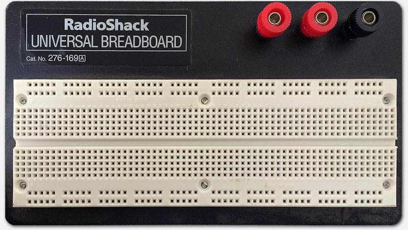
Larger Breadboard I got from RadioShack (6x16cm or 6½”x2¼”)
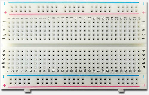
Smaller board that came with Arduino (8×5½cm or 3¼”x2¼”)
Note : some claim that the name “Breadboard” originates from a board used to slice bread, with a bunch of nails hammered into them (not all the way) to wrap wires around and thus experiment with electronics.
As you can see, the top one from RadioShack is much more sturdy to work with, but for tiny Arduino or BASICStamp projects the second (much cheaper) board will often be sufficient. Much larger breadboards do exist, I just didn’t have any laying around for a photo-shoot  …
…
Bottom line with the selection of a Breadboard is: Keep in mind that you can reuse a breadboard for your next prototype project!
In not very common scenario’s, prototypes never get taken apart, or a breadboard needs to “fit” the accessories of particular component(s) you’re using. In those cases you might want to look at a perfect fit. In all other case: do not buy a tiny breadboard – you’ll regret it with future projects.
Note that with the rise of Chinese manufacturers, breadboards have become a lot cheaper, so price does not necessarily need to play a role in your choice. If you look for example at Amazon, you’ll see that a nice sized breadboard can be found for just a few bucks. For that matter, eBay is a great resource for cheap breadboard as well – with either though; make sure you don’t get screwed on the shipping costs!
Anatomy of a BreadBoard
I’ll admit that I was a little confused as well when I started toying with my first breadboard, so here a brief overview how a breadboard works.
As you undoubtedly have noticed: breadboards have a lot of holes. The distance between holes is a standard distance so that components like IC’s (chips) will fit perfectly. This also fits great for standard resistors, capacitors, LED’s etc.
Under the holes we find metal strips which can make contact with the pins of the components or jumpers (wires) we stick into the holes.
These strips connect to multiple pins, but not to all pins (see layout example below).
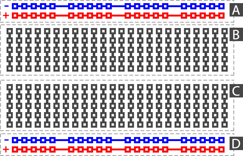
Before we go to the layout, we can think of a breadboard as a board that can be divided in 2 functional areas:
– the power strip(s) (in the drawing below A and D)
– the component grid(s) (in the drawing below B and C)
Note that I made these words up, so don’t consider those “official” terms for these areas.
As you can see below, the “power strips” are horizontally connected (A and D).
To use these strips (optionally), simply connect one of the pins to the minus (or ground/GND) and one to the plus of your power source.
Most breadboards have at least 2 “component grids” (B and C), separated at exactly the distance between the two pin sides of a DIP IC package between B and C.
DIL, or Dual In Line is a standard form factor for IC’s (or Integrated Circuits, or Chips).
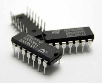
Examples of DIL IC’s (Photo: Kimmo Palosaari)
The pins of the component grids (B and C) are connected vertically, per column, as you can see below.
The grids B and C are not connected with each other.
Note :
– Not all breadboards have a “+” or “–” indicator, which makes sense if you for example work with an alternating current (see RadioShack example above)
– Not all breadboards have the exact same layout or the exact same number of pins (compare both photo’s above)
– Some breadboards (like the RadioShack example) have additional terminals for thicker wires/plugs
– Most breadboards have some kind of numbering system going on which can be used for referencing individual contacts
Your basic solderless breadboard layout
How to use a Breadboard
The connections within a breadboard was for me the first thing that finally made sense out of a breadboard for prototyping. Now that we know how these connection bridges work, time to look how to place components.
Regular Wires
First thing we will use are wires or jumper wires. You can of course use regular wires – just make sure they are solid core wires that are not too thick. Stranded wires are not practical with a breadboard unless you’re good at soldering (tinning) the ends neatly.
Also pay attention to how much you strip the wire … 5 mm is a prefered stripping length.
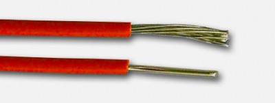
Stranded versus Solid-core wires
Pre-Made Jumper Wires
The advantage of jumper wires is that are available as sets of pre-made cables.
Their ends are solid, at the right length and proper diameter to fit in the holes of your breadboard. This makes it very easy to build or change configurations on your breadboard.
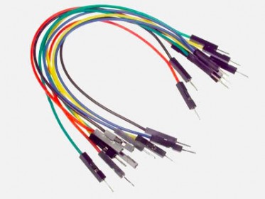
Set of Jumper Wires
Hand-Made Jumper Wires
For certain applications however, jumper wires can be too long and custom made wires should be used. When making your own cables keep in mind that you need to strip about 5mm (approximately 1/5″) of insulation. With very short wires this can of course be a challenge and good wire stripper will be essential.
Hand made Jumper Wires
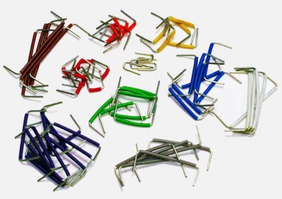
Staples as Jumper Wires
Funny thing is that regular staples seem to fit the pinholes perfectly as well, and can be used (since they’re made out of a conducting metal) as jumpers as well for simple projects.
Staples can be used as short jumper wires
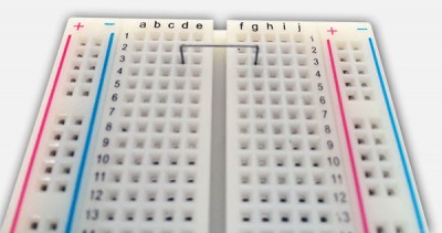
Placing Components
When placing components, you will have to observe the direction of the connected pin holes of the breadboard.
In the picture below:
– the power-strips go from left to right (horizontal red line in the second picture),
– the component grids have strips from top to bottom (vertical red lines in the second picture).
In the example you see a red jumper wire going from the power strip to a vertical component strip.
The red LED and the tiny resistor work from left to right: we “jump” from one vertical line to another.
When looking at the IC (Integrated Circuit), you’ll now see why there are 2 component grids separated at the distance equal to the width of the DIL IC.
In the second picture you’ll see the “hot” pins and how the connect to the components.
Please note that the picture does not represent a working circuit …
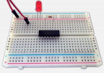
Placing components on a Breadboard
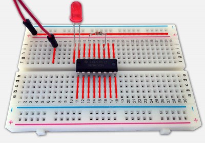
Components on a Breadboard – These pins are connected
Working Example
To illustrate the breadboard in action, I created a very basic example. We’re going to hookup a LED to a 9V battery. The circuit looks like this (never mind the correctness of it all):
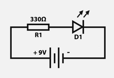
Simple Circuit: LED with a battery
We will need an LED (D1 – any color will do), a resistor (R1 – 330Ω), a 9V battery (or other DC power source) and a few jumper wires.
In the illustration below:
The red and black lines are jumper wires or components. The grey lines are the metal parts in the breadboard that are being used, the “hidden” connections between holes.
If we read the simple circuit schematics from plus to minus:
The plus of the battery goes to one pin of the resistor R1 (resistors have no polarity, so it doesn’t matter which one of the 2 pins you pick).
The other pin of the resistor R1 goes to the Anode pin of the LED D1. The Anode could be seen as the “plus” of the LED which is the longest pin of the LED.
The other pin of LED D1 (the shortest one) goes to the minus.
Anode/Cathode identifiers of an LED:
– Flat side is Cathode
– Large “object” in the LED is Cathode
– Shortest pin is Cathode
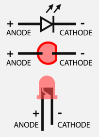
LED Pinout
So on a breadboard that could look like this:
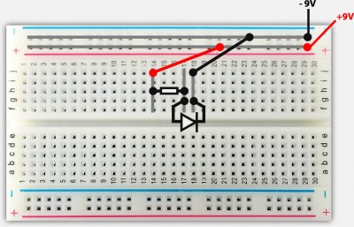
Demo Circuit connections
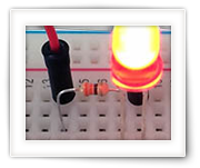
Once you’ve build the circuit on your breadboard, connect the battery (connecting power to your circuit is of course always the last item to connect after a double check if you did everything right) and the LED should light up:
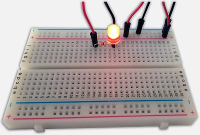
Demo Circuit in Action
And that concludes our simple breadboard introduction.


Comments
There are 5 comments. You can read them below.
You can post your own comments by using the form below, or reply to existing comments by using the "Reply" button.
[…] What is a Breadboard and How to use it […]
[…] //www.tweaking4all.com/hardware/breadboard/ […]
[…] Take a look at this site if you want to learn more about how to use breadboards. […]
For those interested, a great article on: JavaScript for Microcontrollers and IoT: Building a Sensor Hub
Thanks Sebastian!
hans
[…] Sources: … https://www.tweaking4all.com/hardware/breadboard/… […]