Arduino and DS18B20 Temperature Sensor
The DS18B20 comes in different forms and shapes, so you have plenty of choice when deciding which one works best for you. There are 3 variations available: 8-Pin SO (150 mils), 8-Pin µSOP, and 3-Pin TO-92. If you look at eBay or Amazon, some of our Chinese friends have packaged the TO-92 version in a waterproof housing so you can use it directly in your fish-tank, water boiler, outside your house or even your freezer, without having to worry about water/moisture shortcutting your electronics (these have 3 wires: Black (GND), Red (Vdd) and white or yellow (Data)).
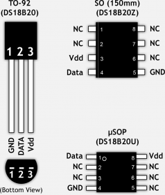
DS18b20 – Available Packages
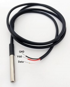
DS18B20 in a waterproof casing
The DS18B20 is quite versatile. It can be powered through the data line (so called “parasite” mode, which requires only 2 wires versus 3 in normal mode), it operates in a 3.0V to 5.5V range, measures Temperatures from -55°C to +125°C (-67°F to +257°F) with and ±0.5°C Accuracy (from -10°C to +85°C). It converts a temperature in 750ms or less to a up to 12 bits value.
Another cool feature is that you can connect up to 127 of these sensors in parallel, and read each individual temperature. Not sure what I’d do with that, but the ability to combine one or two, for example for the temperature of your fridge and freezer, is a nice option, specially when other pins of your Arduino are being used for other things …
Ad Blocking Detected Please consider disabling your ad blocker for our website.
We rely on these ads to be able to run our website.
You can of course support us in other ways (see Support Us on the left).
What we need to get the Arduino and DS18B20 to work
Software
- Of course we will need the Arduino IDE software
- OneWire library for the Arduino and DS18B20 (will save you a lot of work)
- Our own sketch …
The Arduino IDE can be downloaded from the Arduino website (highly recommended), or from Tweaking4All (this version might be outdated by the time you read this article).
The OneWire Library can be downloaded from the OneWire Project Page (highly recommended to get the latest version) or you can download v2.2 from Tweaking4All.
Download - Arduino Windows
Download - Arduino MacOS X
Download - Arduino Linux 32 bit
Download - Arduino Linux 64 bit
Harware
The USB cable is of course only needed to program and power the Arduino during development.
When we run the Arduino computer independent you might want to look for a suitable power supply.
Wiring Arduino and DS18B20
The wiring, this is the beauty of a 1-wire interface, is super simple.
The GND pin of the DS18B20 goes to GND on the Arduino.
The Vdd pin of the DS18B20 goes to +5V on the Arduino.
The Data pin of the DS18B20 goes to a (digital) pin of your choice on the Arduino, in this example I used Pin 2.
The only thing we need to add is a pull-up resistor of 4.7 KΩ. I have seen ther values, but it seems this is the most commonly used value.
The wiring presented below is the regular way of wiring the DS18B20 with your Arduino.
Make sure that you very line 10 and line 65 in the Sketch below to match your data pin and power mode!
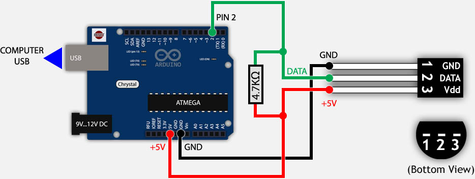
DS18B20 and Arduino wiring
Below a picture of my test setup … it’s really easy.
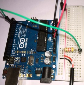
Arduino and DS28B20 setup is super simple …
Parasite Power vs Regular Power
The alternative wiring is called “Parasite” mode, where we do NOT connect the +5V to the Vdd pin of the DS18B20.
Instead we connect Vdd of the DS18B20 to GND. The advantage being obvious: you only need 2 wires.
The downside of parasite mode is that you should limit the number of sensors and the wires should not be too long!
In the end, I’m not sure what to think of the Parasite mode, as I’d like to use this when the sensors are far away from the Arduino, but on the other hand this mode is not very suitable for that. Up to you which you prefer.
Plenty of strange results have been report when using Parasite mode. Therefor I cannot recommend Parasite mode for a reliable setup.
Ad Blocking Detected Please consider disabling your ad blocker for our website.
We rely on these ads to be able to run our website.
You can of course support us in other ways (see Support Us on the left).
Installing the OneWire Library
If you downloaded the ZIP file from either OneWire Project Page from Tweaking4All, then you should be able to use the Library Import option in the Arduino IDE software. From the menu, choose “Sketch” “Import Library” “Add Library” and select the ZIP file you downloaded.
In case this fails :
The Arduino IDE can’t seem to find the proper directory name in the ZIP file, so the easiest then is to unzip the file, make sure the directory is called “OneWire” (which holds the “examples” directory and a bunch of files) and drag it into the library directory of your Arduino IDE.
To find the examples files in the menu’s, you might need to restart the Arduino IDE.
Loading the Sketch
The following Sketch comes with OneWire, so you’ll find it in the ZIP file. If you installed the OneWire Library, the you’ll find it in the examples.
Go to “File” “Examples” “OneWire” and select the “DS18x20_Temperature” example, which will look like the code below.
The code below uses the OneWire Library to conveniently go through all connected DS28B20 temperature sensors (see how to connect multiple sensors at the end of this article) and checks the details of each of them, to then display the data in the debug window (menu: “Tools” “Serial Monitor“).
The output in the debug window will look something like this:
1
2
3
4
5
6
7
8
9
10
11
12
13
14
15
16
17
| ROM = 28 88 84 82 5 0 0 6A
Chip = DS18B20
Data = 1 56 1 4B 46 7F FF A 10 D1 CRC=D1
Temperature = 21.37 Celsius, 70.47 Fahrenheit
No more addresses.
ROM = 28 88 84 82 5 0 0 6A
Chip = DS18B20
Data = 1 56 1 4B 46 7F FF A 10 D1 CRC=D1
Temperature = 21.37 Celsius, 70.47 Fahrenheit
No more addresses.
ROM = 28 88 84 82 5 0 0 6A
Chip = DS18B20
Data = 1 56 1 4B 46 7F FF A 10 D1 CRC=D1
Temperature = 21.37 Celsius, 70.47 Fahrenheit
No more addresses. |
Regular Power or Parasite Power?
The DS18B20 can work in a regular mode or in a so called Parasite mode.
The normal mode requires 3 wires, whereas the Parasite mode uses only 2 wires.
You will need to set the right mode to get correct temperature readings:
For Parasite mode line 65 should read: ds.write(0x44, 1);
For Regular mode line 65 should read: ds.write(0x44);
Make sure you set the right data pin!
In line 10, where it says “OneWire ds(2);” the data pin to be used is set.
In this example I used pin 2, however the default setting in the example that comes with OneWire uses pin 10.
(I had other plans for pin 10, so I did set mine to pin 2)
1
2
3
4
5
6
7
8
9
10
11
12
13
14
15
16
17
18
19
20
21
22
23
24
25
26
27
28
29
30
31
32
33
34
35
36
37
38
39
40
41
42
43
44
45
46
47
48
49
50
51
52
53
54
55
56
57
58
59
60
61
62
63
64
65
66
67
68
69
70
71
72
73
74
75
76
77
78
79
80
81
82
83
84
85
86
87
88
89
90
91
92
93
94
95
96
97
98
99
100
101
102
103
104
105
106
107
108
109
110
111
112
| #include <OneWire.h>
// OneWire DS18S20, DS18B20, DS1822 Temperature Example
//
// http://www.pjrc.com/teensy/td_libs_OneWire.html
//
// The DallasTemperature library can do all this work for you!
// http://milesburton.com/Dallas_Temperature_Control_Library
OneWire ds(2); // on pin 2 (a 4.7K resistor is necessary)
void setup(void) {
Serial.begin(9600);
}
void loop(void) {
byte i;
byte present = 0;
byte type_s;
byte data[12];
byte addr[8];
float celsius, fahrenheit;
if ( !ds.search(addr)) {
Serial.println("No more addresses.");
Serial.println();
ds.reset_search();
delay(250);
return;
}
Serial.print("ROM =");
  for( i = 0; i < 8; i++) {
    Serial.write(' ');
    Serial.print(addr[i], HEX);
  }
if (OneWire::crc8(addr, 7) != addr[7]) {
Serial.println("CRC is not valid!");
return;
}
Serial.println();
// the first ROM byte indicates which chip
switch (addr[0]) {
case 0x10:
Serial.println(" Chip = DS18S20"); // or old DS1820
type_s = 1;
break;
case 0x28:
Serial.println(" Chip = DS18B20");
type_s = 0;
break;
case 0x22:
Serial.println(" Chip = DS1822");
type_s = 0;
break;
default:
Serial.println("Device is not a DS18x20 family device.");
return;
}
ds.reset();
ds.select(addr);
ds.write(0x44); // start conversion, use ds.write(0x44,1) with parasite power on at the end
delay(1000); // maybe 750ms is enough, maybe not
// we might do a ds.depower() here, but the reset will take care of it.
present = ds.reset();
ds.select(addr);
ds.write(0xBE); // Read Scratchpad
Serial.print(" Data = ");
Serial.print(present, HEX);
Serial.print(" ");
for ( i = 0; i < 9; i++) { // we need 9 bytes
data[i] = ds.read();
Serial.print(data[i], HEX);
Serial.print(" ");
}
Serial.print(" CRC=");
Serial.print(OneWire::crc8(data, 8), HEX);
Serial.println();
// Convert the data to actual temperature
// because the result is a 16 bit signed integer, it should
// be stored to an "int16_t" type, which is always 16 bits
// even when compiled on a 32 bit processor.
int16_t raw = (data[1] << 8) | data[0];
if (type_s) {
raw = raw << 3; // 9 bit resolution default
if (data[7] == 0x10) {
// "count remain" gives full 12 bit resolution
raw = (raw & 0xFFF0) + 12 - data[6];
}
} else {
byte cfg = (data[4] & 0x60);
// at lower res, the low bits are undefined, so let's zero them
if (cfg == 0x00) raw = raw & ~7; // 9 bit resolution, 93.75 ms
else if (cfg == 0x20) raw = raw & ~3; // 10 bit res, 187.5 ms
else if (cfg == 0x40) raw = raw & ~1; // 11 bit res, 375 ms
//// default is 12 bit resolution, 750 ms conversion time
}
celsius = (float)raw / 16.0;
fahrenheit = celsius * 1.8 + 32.0;
Serial.print(" Temperature = ");
Serial.print(celsius);
Serial.print(" Celsius, ");
Serial.print(fahrenheit);
Serial.println(" Fahrenheit");
} |
How to connect multiple Sensors
The DS18B20 Digital Temperature sensor allows you to set multiple in parallel. When doing this, the OneWire library will read all sensors.
Below I’ve illustrate 2 ways of wiring your sensors for bth methods of powering the sensors.
For larger networks of sensors (more than 10), using smaller resistors should be considered, for example 1.6 KΩ or even less.
It has been observed that large amounts of sensors (more than 10) in the same network can cause issues (colliding data), and for that purpose an additional resistor of say 100 … 120 Ω should be added between the data line to the Arduino and the data pin of the sensor, for each sensor !
The output of the previous demo Sketch for 2 sensors could like this:
1
2
3
4
5
6
7
8
9
10
| ROM = 28 88 84 82 5 0 0 6A
Chip = DS18B20
Data = 1 51 1 4B 46 7F FF F 10 FE CRC=FE
Temperature = 21.06 Celsius, 69.91 Fahrenheit
ROM = 28 DA CA 27 5 0 0 49
Chip = DS18B20
Data = 1 4E 1 4B 46 7F FF 2 10 D9 CRC=D9
Temperature = 20.87 Celsius, 69.57 Fahrenheit
No more addresses. |
Selecting the right sensor
It would be nice to know what sensor result you’re looking at when using multiple sensors. So how do I identify the right one?
Serial Number
Since these sensors are digital, they do have a serial number, which can be used to identify from which sensor the originated.
All nice and dandy of course, but you’d need to know the that serial number first, right?
The debug output from our example sketch provides exactly that as a 64-bit serial number (the “ROM” value), for example:
28 88 84 82 5 0 0 6A or 28 DA CA 27 5 0 0 49 in the example output above.
Again: It is suggested, for a large amounts of sensors (meaning 10 or more), to add a 100 … 120 Ω resistor between DS18B20 data pin and Arduino data pin (for each sensor!) to improve reliability. I can’t provide any experience concerning this, as I have only 2 sensors … for now.
Normal Power Mode
Below you will see how we can set multiple sensors in parallel using the regular powermode.
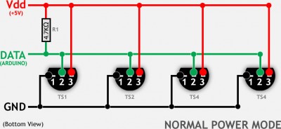
DS18B20 – Multiple sensors in Normal power mode
Parasite Power Mode
Parasite mode basically drops the wire for Vdd and shorts pin 1 and 3 of the sensor, and the sensor will pull power from the data pin.
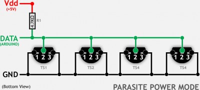
DS18B20 – Multiple sensors in Parasite power mode
Ad Blocking Detected Please consider disabling your ad blocker for our website.
We rely on these ads to be able to run our website.
You can of course support us in other ways (see Support Us on the left).
More Resources
Below a list of practical resources, some offering very detailed technical information.


Comments
There are 107 comments. You can read them below.
You can post your own comments by using the form below, or reply to existing comments by using the "Reply" button.
This would be great to add to the raspberry pi. Maybe combine both the ambilight and this to use with an overclock raspberry pi since an arduino has more power than the ws2801 need. Just a thought. Great work man. Your guides are great. Very informative. Keep up the good work
Willy
Thanks Willy! Much appreciate it!
I’m sure the Arduino can handle a sensor next to the boblight (if it doesn’t screw up timing too much). Then again … maybe the Raspberry Pi might be able to pull it off on itself as well. Are you thinking overheating detecting?
I’m working on expanding the project in this article, by adding an Ethernet interface … works already pretty good!
hans
Yesterday I added an article for a cheap Ethernet connection, and today one on how read sensor data over the network …
hans
How much can I get good days come easy .. 4 sensor information from all of them tied separately. Examples ..
1.sens 15
2.sen 20
3.sens 8
4.sens 35
Can you help?
serafettin
Hi Serafettin,
I understand that you’re using 4 different sensors, independently? Meaning you’re testing them one at a time, yet you get very random results?
If that’s the case;
– Verify the conversion code?
– I’d consider contacting your hardware supplier, there seems to be something wrong?
– Are the sensors identical?
With the sensors I have, I do see a tiny discrepancy between two sensors, but that’s about 0.1 degree … which I do not consider an issue, and is not nearly as bad as what you have observed.
hans
Hi Serafettin,
I received a reply from you by email, but was unable to read … I only speak English, German or Dutch …

Also; please do not reply by email, since I won’t be able to reply here (could be useful info for others) ….
hans
Do you have a version using an LCD Display 12X4, 16X2 or 20X4
I would very much appreciate this
Thank you in advance
jeffrey Stuart
Hi Jeffrey!
Well, I do have such a display available, and I like the idea of extending this article with such a display.
However, my display is laying at home and I have been traveling a lot the past few months. So I’ll have to wait until I’m home again to work with that, or order an Arduino, Temp sensor and Display while traveling …
Let me see which one comes first ….
….
hans
[…] links that helped me created this build. Arduino Ethernet – Pushing data to a (PHP) server How to measure temperature with your Arduino and a DS18B20 Brick-Temperature-DS18B20 Arduino Starter Kit Example […]
Cool project! :-)
hans
Keep in mind that the pin diagrams for the DS18B20 in the wiring diagrams are oriented with you looking at the pins from the bottom. Made the mistake of misinterpreting the diagram and accidentally made a sensor unhappy by plugging it in backwards. Hope this helps!
Taz
Thanks Tax for the tip!
It is most certainly helpful for others!
hans
Hi all,
Very nice tutorial, thanks. I would try to make a dashboard with dweet and freeboard like this one. Can somebody help me with this or direct me to some other tutorial? I have 5 Temp Sensors at the moment, 2 HMC5883L Magnetometer are comming later (i want to check the on/off status of my heating pump).
Thanks and BR
Viktor
Viktor
Hi Viktor!
Sounds like an awesome project!
I can’t really help too much right now as I have yet to start a project with dweet.io or freeboard.io, the link you provided does seem to cover quite a bit though.
The widget looks very slick, so I might take a look at that one of these days.
Hopefully other user can chime in here?
hans
Hi, My name is Elson Avallone and I’m Phd student at Universidade Estadual Paulista “Júlio de Mesquita Filho” – UNESP Bauru. I would like to have autorization to use your Arduino programm system and also to put it in my thesys.
Please send me your answer
Elson Avallone
Hi Elson,
feel free to use the information in this article for your thesis.
Please mention the source if possible.
Good luck with your thesis – I know how much work that can be …
hans
how to make program on pir sensor plus temperature sensor?? when the temperature sensor state on the lcd player at 27 degree celcius,the pir sensor will not work eventough the person walk through it but when the temperature is below then 27 degree celcius,the pir sensor will work normally….
deen
Hi. Is it posible to have this read the temp then Tweet it?? I’d like to try building it…but I have NO experience with Arduino or coding :(
Sal Ciampa
Hi Sal!
Ehm, I have never done it, but you should be able to do it.
Take a look at these two articles: Arduino ENC28j60 ethernet, and Arduino Ethernet Data-push.
Now neither of these two articles will show you how to Tweet, but will show you some of the network basics.
To be able to Tweet, you’d need to probably consult libraries like Tweet-library for Arduino, or this Twitter Library (seems to have more details). In the end; the temperature is just text, so I’d assume that with help of these libraries you’d be able to Tweet them.
Possible issues might be running out of memory on for example a Nano or an Uno. You might have to resort to a Arduino Mega.
Hope this help …
hans
Hi
I want print a value from 237 in 23.7. Can you that explain to me.
greetings from holland
Joop
Joop van Schaik
Hi Joop!
Good question, I’m carefully assuming you mean: how to print a floating point number to serial …
(I’m sure you figured out how to divide 237 by 10 to get 23.7 on your own haha).
There are no “easy” tricks to do this, but you could consider using the function dtostrf().
Untested example (not having my gear near me), but it should be something like the code below.
No special include needed as far as I recall.
Hope this helps … there are other methods.
hans
Thank you for good sharing!!!
I could work these program.
I want to connect processing with this one.
How could I do that?
Ray
Hi Ray!
Thanks and you’re welcome!
I’m not sure what you mean with “I want to connect processing with this one.”?
I’d like to help if I can, but maybe you could provide more info (if you think this might become a long topic; please consider using the Forum otherwise the comments become swamped with a lot of off-topic information).
hans
I want a analog input
Ray
Hi Ray,
for Analog Temperature reading you’d need a different sensor. For example a TMP35 or TMP36.
I have not [yet] played with these though.
Some good resources:
I’m not sure if calibration might be needed as well.
hans
Hi there..
Firstly thanks for taking the time to put together this detail. I have a question that I hope you can help with. when I run the code it reads the temperature as -43’c. I have tried 3 different sensor all with the same result. If heat the device the temperature raises inline with the heat source. I ahve check that I am not using parasitic power mode and have checked the code reflects that.
This is driving me mad so any thoughts you have would really help.
Cheers
Owen
Owen Luke
Hi Owen,
that indeed sounds like something that would annoy me too.
I’d check a few things first:
1) Start with one sensor
2) Make sure you’re using the right pins on the sensor and Arduino
3) If that doesn’t work; try a different pin on the Arduino (adapt code!)
Is it always giving -43C?
hans
Hello,
I want to monitorize 6 sensors and show their temperature in a htlm page.
I have all the code, but i just see the temperature of one sensor.
Can you help me?
Francisco Silva
See this forum post.
Francisco Silva
Hi Reply Francisco,
I moved your question and code (due to it’s size) to the forum.
I’m traveling at the moment so I might not be able to get to answering your question right away, but you’ll find it in the forum: this post.
hans
Hello Hans,
Thanks for your aswer.
How can i get the adress of the 6 sensors?
And put the temperature in each one correspondely, by a variable.
Francisco Silva
You’d only need to modify the code (see the forum post).
If you’d prefer to see variables, then you’d need to work with passing a dynamic array to the function, making things a little cleaner but more complicated.
hans
Beware of our Chinese friends .. sometimes the waterproof sensors come with a different default resolution.
Setting it to 12 bit goes like:
After storing in eeprom 12 bit will be loaded as default. So the code is only needed once.
Henk
Hi Henk!
Awesome info! Yeah our Chinese friends tend to screw around with imitation which sometimes miss the marker.
This is good info! Great catch!
Did the sensor model you used have a different identification number/model?
hans
Hi Hans,
No, nothing special about them, just the unmarked waterproof version. I ordered 5 of them, and all had the same 9-bit setting.
Our Chinese friends are very inventive, but they do produce a lot of fake items.
Try the MAX7219 LED driver .. it has even a different pinning than the original.
And the protection diodes they use on some modules introduce a 1 V drop. Add that to the 0,3-0,5 V
a Nano introduces when powered from USB and instead of 5 V your module runs on 3,5 V. It than does either not run at all, or
is very unstable.
There are many more examples where modules/IC’s are not a drop-in replacement for the original.
So IMO unless you understand electronics and are able to read a datasheet do not order from China.
Things might not work as expected .. very frustrating if you just want to play with the Arduino environment.
Regards, Henk
Henk
Yeah I know, that’s why I more and more opt for the “original” products.
I have seen quite a few LED strands and Arduino boards as well, almost identical, but just not quite and enough to cause issues.
Thanks again for the info Henk!

Have a happy New Year!
hans
Hi.
How to do it, I know the address?
28 88 84 82 5 0 0 6A
I do not want her to retrieve
Miro
Hello Miro!
I assume you mean that the sensor with serial number “28 88 84 82 5 0 0 6A” is connected, but you would not want it to be read?
I’m not having access to any of my tools right now (I’m traveling), but it would be something like the following.
To avoid reading it, you should capture the data from this section of code, into a string, say mySerialNumber (so modify the code here to create a string instead of printing it to serial):
Serial.print("ROM =");for( i = 0; i < 8; i++) {
Serial.write(' ');
Serial.print(addr[i], HEX);
}
and put and if … then … around line 38 to 111.
Something like
if (mySerialnumber!="28 88 84 82 5 0 0 6A") { // just before line 38.... // lines 38 - 111
} // just after line 111
hans
Hi.
If you do not want.
Something like that.
http://henrysbench.capnfatz.com/henrys-bench/ds18b20-arduino-user-manual-introduction-and-contents/ds18b20-arduino-users-manual-part-3-reading-a-single-temperature/
I’d like to do with this code and calling functions
float temperatura (“28 88 84 82 5 0 0 6A“) {
}
DallasTemperature.h not good.
Too slow.
I am sorry.
I am a beginner.
Miro
Oh now I see what you mean (don’t apologize for being a beginner, we all are or have been there as well ).
).
I’d have to take some time to write something like that. Unfortunately, I’m traveling, so I’m a little limited in what I can do.
I’d need my Arduino and Temp sensor to do some tests.
Just in my head, untested, the code on the link you posted, pretty much does what you’re looking for:
The trick is to be found in this little piece of code:
The property call “DallasTemperature::toFahrenheit(tempC)” will convert it to Fahrenheit if needed.
hans
Hi
Great string of information and reply’s for a newbie like me to learn from. Appreciate your time.
I have a string with 9 of the DS18B20 using +5v power (not parasite)
I would like to use the Dallas library as above but want to assign the 9 sensor temp values (in Fahrenheit) to 9 unique integer variables (don’t need decimal accuracy) to pass to further code further down the Sketch. (controlling a relay board by temperature to run fans and furnaces)
Thinking there is a way to do a counter loop to automatically create the variables and sequentially or by address assign the values. (something like kT1 to kT9). (Would be nice to be able to replace a bad sensor and the code would be able to update the serial # and keep working. Not sure can keep sensors in order and assigned to the right variable so it is in the same physical place on the string)
Having all the sensors show up in the monitor is nice as well for troubleshooting.
I have all the libraries and some code but having a problem getting all the software modules to work together. Any chance you could take the code above and suggest how to get it to work with the 9 sensors sent to unique variables?
Many thanks
GAry
GAry
Hi Gary,
Let me see if I can help (sorry for the late response).
The only way I can see this to work would be by storing the serial numbers so we can link them to your code or designated name for a given sensor.
In line 32 you see how the serial number of a sensor is being read
Serial.print("ROM =");for( i = 0; i < 8; i++) {
Serial.write(' ');
Serial.print(addr[i], HEX);
}
After a first run we could make an array, to define the serial numbers and the matching sensor names, something like this in the beginning of the code (before “void setup()” and fill in your own serial numbers and sensor names of course):
char *SensorSerials[]={"28 88 84 82 5 0 0 6A", "28 88 84 82 5 0 0 6A", "28 88 84 82 5 0 0 6A", "28 88 84 82 5 0 0 6A", "28 88 84 82 5 0 0 6A","28 88 84 82 5 0 0 6A","28 88 84 82 5 0 0 6A","28 88 84 82 5 0 0 6A","28 88 84 82 5 0 0 6A"};char *SensorLabels[]={"Sensor1", "Sensor2", "Sensor3", "Sensor4", "Sensor5", "Sensor6", "Sensor7", "Sensor8", "Sensor9"};
Now that part at line 32 that I just showed, should be modified as well, so that we catch the serial number in a variable. After that, compare the read information with the serials in the SensorSerials, so we can find which one is the right one. For whatever number in the array it matches, for example #4, we can now pull the name from the other array. Inn the example this could be Serial.print(SensorLabels[4]);.
It will take a little reading up on for loops, arrays and strings, but feel free to ask if you need assistance with that – or even better: start a forum topic so we can post code examples and such (see the Arduino Forum).
hans
You do not use function DallasTemperature.
DallasTemperature function is not good.
Too slow.
Only functions OneWire.
Miro
I have not been able to test it …
If it’s too slow then one could use:
hans
I’ve used a DS18B20 wired to a PL2303TA USB adapter and it works great, however
the 4.7k resistor doesn’t go between Vdd and Data, but in between Vdd in on the DS18B20 and Vdd out from the PL2303TA.
I’m wondering if that’s going to cause any issues,- it seems to work though.
Martin
Hi Martin,
I have no experience with the PL2303TA … maybe one of the visitors/users of Tweaking4All can give you info.
As far as I can see, if the readings you’re getting are right, then I probably wouldn’t worry too much about it.
hans
integrate NI RTD and arduino for temp variation
chffh
As far as I know (for more info, see this link), an RTD is a resistance temperature detector, which means the resistance changes as temperature changes. This is obviously not done in the same way as described here. A good article on how to wire it to an Arduino and an example sketch can be found at OpenEnergyMonitor.org.
Hope this helps?
hans
[…] //www.tweaking4all.com/hardware/arduino/arduino-ds18b20-temperature-sensor/ […]
hi..im new in arduino
question : after i Go to “File” “Examples” “OneWire” and select the “DS18x20_Temperature” example, which will look like the code below. should i to verify or compile this onewire
ismail
You can always try code.
I just looked and it looks a lot like the code I have – I think it will work just fine.
hans
what mean if on my serial monitor shown “no more addresses”
ismail
Hi Ismail,
it means that the Arduino couldn’t find any more temperature sensors.
The OneWire library (ds) will look for device addresses, and when it cannot find one, or is done with all the sensors, it will say just that.
hans
It works great, thanks!
Now I would like to use the data in this way: it should start a fan that is controlled by a mosfet p30N06LE at a certain fixed speed
How do I couple the data coming from the DS18B20 with the fanspeed sotware? Is this e.g by setting if Temperature >35 then set pin 3 255
Or can you recommend a place where to find this
Paul
Hi Paul!
Great to hear it works!
As for setting your fan speed through a pin, ehm … I’m afraid the Arduino does not allow analog output (see also PWM and AnalogWrite), then again, it might work with what they call PWM.
As for “linking” temperature to fan speed;
You could, if you figured out if AnalogWrite/PWM would work for you, use indeed an if statement, around line 108, something like:
if(celsius>35) {...
}
or with multiple if’s (assuming you’re talking Celsius, otherwise use the variable “fahrenheit”):
if(celsius>35) {analogWrite(3, 255); // fan speed highest
} else if (celsius>30) {
analogWrite(3, 200); // fan speed lower
} else if (celsius>25) {
analogWrite(3, 100); // fan speed even lower
} else if (celsius>20) {
analogWrite(3, 50); // fan speed slowest
} else {
analogWrite(3, 0); // fan OFF
}
hans
Hi Hans,
thanks very much for your answer, it works now. I took a pretty low value in analogWrite (115) and a big capacitor to filter the noise of the PWM.
Paul
Thanks Paul!
Glad to hear you’ve gotten it to work to your liking! Nice!
hans
Thanks for this article, i have a shield with a LCD monitor i want to display data from the sensor on. But only pin that is available for sensor is pin 13.
Cant seem to get the sensor to work at pin 13 on my UNO. Can you please help me?
Thanks
Johan
Johan
Hi Johan,
Did you try using pin 2 for the sensor?
(or another free pin)
hans
Pin 2 works but as i said only pin available is 13..
Johan
Oops, my bad, …
Pin 13 will not work for OneWire, since the “internal” LED is already connected to that one (source).
Is there any way you can make another pin available? Ie. swapping them?
Not sure what all the other pins are used for.
hans
Hi, im having troubles whit my sensor..
in my serial monitor i got
No more addresses.
No more addresses.
No more addresses.
No more addresses.
Any sugestions ? TY
DaniM
Hi DaniM!
By the look of it, this can be caused for 2 possible reasons;
1) The wiring isn’t done correctly (Data vs Power) of the sensor,
2) You’re having a Chinese “clone” sensor, which responds differently than the regular DS18B20, see for example this comment.
hans
If I wanna used the i2c to show the temperature how I make this?
Richard Ribeiro
Hi Richard,
honestly, I wouldn’t know,… not to say that it’s impossible, I just really wouldn’t know.
Maybe one of the readers here can chime in if they know more details about using I2C for the sensor.
hans
hi
when I connect ds18b20 to arduino after the upload the program first arduino blink then off
why????
mostafa
I’m sorry Mostafa, I’m not sure what you mean.
You upload the sketch and after that you connect the sensor to the Arduino?
hans
Can this code be compatible with Arduino 101? I keep receiving an error when compiling to the 101 board.
Marie
Hi Marie,
I have not had the opportunity to play with the Arduino 101, so I am not be able to confirm if the code should work or not.
I do know the 101 uses a different processor (Intel vs ATMega) – but I would not expect this to be a problem.
What is the error message you’re seeing?
hans
I imported the OneWire library from the .zip file per the instructions. I try to compile the DS18x20_Temperature code and get the following result:
collect2.exe: fatal error: cannot find ‘ld’
compilation terminated.
exit status 1
Error compiling.
Do you know what the problem could be?
Ed Symons
Hello Ed,
this seem to be a problem seen by others as well – even though I never ran into this. I’m working on a Mac though.
It seems to be related to the Linker (part of the compiling process) – see also this topic in the official Arduino Forums.
I do not know if this is specific for a particular Windows version (XP) or not … but one user claims that this fixed the problem for him:
Some users claim it’s Windows XP related, others have narrowed it down to the Arduino IDE version (check if you have the latest version).
Hope this helps a little bit … please let us know if you found what fixed this.
hans
I already had 1.67 installed and was using that ok except for the problem described. I tried installing the 1.67 version posted instead and that worked. I am running Windows 10.
Ed Symons
Cool! So basically re-installing fixed the issue?
hans
hi may i know if i want to combine 2 temperature sensor which is LM35 and thermistor using arduino, how to do this because im so new in coding.All helps here are very appreciated.tqvm
faz
Hi Faz,
I have never worked with the LM35, but found this reference on the Arduino.cc website.
Looks like reading one or two LM35’s shouldn’t be too hard.
Hope this helps – since I do not have an LM35, I was unable to test this.
If you’d like to discuss the code, feel free to start a forum topic …
hans
[…] Tweaking4All.com […]
why when i try in my serial monitor just appear ” no more addresses”?
help me please…
rahmat
Hi Rahmat,
could it be that your router cannot handle more clients?
I have never seen this error, so I can only guess that the DNS of your router doesn’t have any IP addresses left available.
hans
I don’t now why but when I insert +5V wire arduino uno go down!
Short Circuit ?
I don’t now, but wiring is correct and I Try 3 dsb120 (chinese) with some issue.
Any idea?
Raffaele
raffaele
Hi Raffaele,
I assume you triple checked the wiring?
When the Uno goes down I can imagine +5V shorting with GND which results in no more power = Uno shutdown.
And your power supply will not like that too much.
hans
So, I’ve been at this for a while now and have a very weird problem.
I can read from one sensor fine, but once I try to use two sensors, only sensor 2 works correctly while sensor 1 displays 127.81 degrees (not -127).
I have wired them up for normal power mode. Now here comes the weird part. If disconnect the 5V from sensor 2 (the one working correctly) suddenly both of them display the correct temperture.
Since you wrote that parasite power mode can cause problems I dont know if I should leave it like that…and since one of them is still connect to 5V I dont know if it even is parasite mode or some weird hybrid.
Jens
Hi Jens,
it sounds like you’re using a weird hybrid version of the parasite mode.
I should not recommend this, but I’d use it like this for a while and see what happens.
Or rewire for Parasite and see if that makes a difference. Interesting finding though,.
hans
Hans, Thank you for all you do you guru (I’m a poet too!).
Is there a way to transmit data it this format from the DS18B20.
07.99 not 7.99?
Having trouble with a color change on the label text.
Using:
Atmega328P-PU chip,
DS18B20 temperature sensor,
HC-05 Bluetooth module,
MIT App Inventor 2,
Android tablet to display the temperature real time.
Thanks,
-Rob
Rob
Hi Rob,
you could try two different solutions, both padding numbers.
Since you mention that you’re using Bluetooth etc, you might want to look at other options as well. (for example StringToFloat),
Option 1:
If the temperature (assuming you want 2 digits) is below “10”, print an extra “0” before printing the actual temperature.
The same approach could be used for variables as well of course (store the float as a string, add a zero in front if temperature is less than 10).
Serial.print(" Temperature = ");if(celsius<10) { Serial.print('0'); }
Serial.print(celsius);
Serial.print(" Celsius, ");
Option 2:
There are several formatting “print” functions like sprintf() etc, which do not appear all that well documented. I did find this article though, suggesting something like this:
I have to admit though that I have not tested this option.
Hope this helps.
hans
Thanks for the reply Hans,
I found that decimal point itself was not being considered as a number but rather a letter.
This was confusing the application and causing the problem.
Problem solved in MAI2.
Thanks again,
-Rob
-Rob
Awesome!
hans
hi,
Trying to program my UNO to display 8 temperaturevalues to fixed places on a LCD (20×4), I have two problems :
1. I don’t need TWO decimals, but only ONE. How can I fix this ?
2. trying to store serialnumbers, I always find 15 positions instead of 13 as the example given by you on the 12th of august 2017.
examples : 28FF6BBB2174801, 28FF77DF2174439, 28FF1E8A5163ED2 ;;;;
jacques
Hi Jacques,
for question 1, see also the comment/question by Rob just above yours.
I did find some other tricks that might be helpful;
– Use println (see println() documentation – not sure how you send data to your display, over serial?)
– You could try this approach as well (untested) by using the String object (see String documentation):
As for your second question;
I can only guess that things are doubling up somehow? Are there duplicates serialnumbers? (8 sensors, count 0…15 would be twice the number)
hans
It’s the first time I try to program an Arduino….So sorry for “stupid” questions…
After including LiquidCrystal.h and LiquidCrystal lcd(rs, en, d4, d5, d6, d7) in the start of the sketch.
in SETUP I have : Serial.begin(9600) and Lcd.begin (20, 4)
I succeed to control my lcd.display perfectly for the characters and their positions on the lcd.display.
But, using “Lcd.println,”, I see strange vertical stripes between the characters . I suppose this command is not suitable for LCD.
The problem behind my question is :
I intent to write 4 temperatures per line, with a blank area between them. As I have only 20 positions, I can only maintain one decimal after the comma.
Example of what I’d like to see on the display : 19,5 20,5 21,7 22,3.
All temperatures are >10 and < 85
(I want to control the watertemperature IN and OUT of the central heating and IN and OUT watertemperature for the tubes in the floor heating.)
Thanks for your help !!!
wkr
jacques
first off; there are no stupid or silly questions … so always feel free to ask.
I do not have an LCD display like that available at the moment, but I think we can get something done by creating the proper string.
So here my first suggestions: Did you try LCD.print()? (instead of println – or was that just a typo?)
The println function will send one (or maybe even two) extra characters, which might show as the vertical stripes you’re referring to.
A more complex option might be by using the String object, something like this:
void setup() {
  Serial.begin(9600);

  float temp1 = 62.345;
  float temp2 = 72.678;
  float temp3 = 73.06;
  float temp4 = 60;

  String myLCDtext =  String(temp1, 1)+String(' ')+String(temp2, 1)+String(' ')+String(temp3, 1)+String(' ')+String(temp4, 1);
  Serial.print(myLCDtext);
}

void loop() { }
I just created a simple piece of code to test it. The output should be “62.3 72.6 73.0 60.0”.
We basically define the variable “myLCDtext” as a String object and right away assign the values to that object. Since it expects Strings, each “String(temp1, 1)” grabs the variable (temp1) and converts it to another String object (ditto for the spaces).
Of course the Serial.print line will become Lcd.print in your project.
I’m sure there is a more efficient way of doing this, but this seemed like the easiest to implement and understand.
Hope this works for your project.
hans
as for my second question : I wonder why I always receive 15 characters for each serial instead of 13 as in the example you give to Gary for designating names per sensor.
Can that be correct ?
jacques
Hi,
additonal information for the former message :
Lcd.print(celsius,1);
is perfect to obtain only one digit after the comma. So this problem is solved.
jacques
Haha, sorry I didn’t read this message yet … nice!
hans
Hey,
als ik het voorstel dat je eerder aan Gary gaf, opneem in mijn sketch en zoals gevraagd de lijnen….. “char* SensorSerials[]={“28 FF 77 DF 2 17 4 43”, “enz”, “enz”} overneem, krijg ik de foutmelding : warning : deprecated conversion from stringconstant to “char*” [-write-strings].
Ik heb 8 sensors, en krijg dus 8 x de opmerking.
Wat doe ik verkeerd ?
Ik wil de temperatuur van die 8 sensoren om beurt uitlezen en elk resultaat op een vaste plaats printen op mijn LCD-scherm. (20×4)
Bedoeling is Delta T weergeven van IN en UIT van mijn vloerverwarmingsbuizen : IN en UIT komen dan boven elkaar op het scherm en daaronder de Delta-T : het verschil tussen beide)
THANX voor uw hulp
jacques
jacques
Hi Jacques,
ik ga even in het Engels antwoorden, omdat de meeste bezoeker hier in het Engels werken.
I just noticed that this might be caused by a typo in the code I gave Gary. “char* SensorSerials” should actually be “char *SensorSerials” (ie. space should be in front of the asterisk and not after the asterisk).
Since your 3rd row will be the temperature differences (delta), I would assume that these will be below 10, so you might run into a display issue again.
A good reference is the Arduino String Object reference page.
You might want to convert each delta to a string, and if length of each string is not 4 characters then add a space (or zero) in front of it. After that glue them all together again.
Something like this (can be done more efficient, but this way it’s easier to understand – also note that unlike the previous example, I declared the String variable before assigning values which is the more correct way of doing it);
void setup() {
  Serial.begin(9600);
  float temp1 = 2.345;
  float temp2 = 12.678;
  float temp3 = 3.06;
  float temp4 = 10;
  String myLCDstr;
  String temp1Str;
  String temp2Str;
  String temp3Str;
  String temp4Str;

  if(temp1<10) {
    temp1Str = String(' ')+String(temp1, 1);
  } else {
    temp1Str = String(temp1, 1);
  }

  if(temp2<10) {
    temp2Str = String(' ')+String(temp2, 1);
  } else {
    temp2Str = String(temp2, 1);
  }

  if(temp3<10) {
    temp3Str = String(' ')+String(temp3, 1);
  } else {
    temp3Str = String(temp3, 1);
  }

  if(temp4<10) {
    temp4Str = String(' ')+String(temp4, 1);
  } else {
    temp4Str = String(temp4, 1);
  }


  myLCDstr =  temp1Str+String(' ')+temp2Str+String(' ')+temp3Str+String(' ')+temp4Str;
  Serial.println();
  Serial.print(myLCDstr);
}
void loop() { }
Feel free to ask if you have more questions … or need help with the answers I wrote.
hans
Dear Hans,
As asked for I changed the position of the “*” from after char to before SensorSerials. But the error I get is still the same : “warning: deprecated….”
Do you have another suggestion ?
THANKS for your work !
jqs
jacques
Hi Jacques,
ik zit nog even verder te kijken. Als eerste: de warning stopt het compileren niet, is er dus nog een error melding die volgt en het compileren stops?
Nog iets: draai jij de Arduino IDE onder Windows? in dat geval even kijken dat je de meest recente versie hebt.
Wat je ook kunt proberen is
char* SensorSerials[]={“28 FF 77 DF 2 17 4 43”, “enz”, “enz”}vervangen door
const char* SensorSerials[]={“28 FF 77 DF 2 17 4 43”, “enz”, “enz”}(the latter I have not tested and found it in the arduino.cc forum)
hans
Hey Hans,
THX for your info.
I verified the version of my IDE : it’s 1.8.5. I think this is the last one. Isn’t it ?
Your proposal to replace “char* SensorSerials[]= …” by “const char* SensorSerials[]=….” was succesfull : the warning-for-error-message “deprecated conversion…” disappaired.
Now I’m again motivated to go further building my program !
THX a lot !
jqs
jacques
Hi Jacques!
Thanks for the confirmation!

My gear is tucked away still since I moved to Houston, so some of these things I have to do without testing.
Thanks again!
hans
Hey,
as I didn’t succeed to finalize my program, I asked my son in law to help me.
Now my my program is finalised and is working as it was intended to do.
I have no problem to send the sketch, but I don’t know how to do.
Wkr,
jacques
jacques
Hi Jacques,
glad you’re program is working!
You can open the .ino file in notepad, copy the text and paste it in a comment.
Or reply to this notification email and attach it, I don’t mind pasting it for you.
hans
Hey Hans, I know that I’m late for the party. But do you have tried it and get the data wirelessly via wi-fi? Currently I’m using Processing (GUI software and same as Arduino IDE) to show the data. It can work on serial port but I’m facing a problem when I want to connect wirelesly. Now I just know about blynk and it seem more simple to work with and of course wifi problem because they do the part for us but I just don’t know what the important coding that translate the input to output value. Thanks for your time.
Muhammad Syafiq
Hi Muhammad,
No unfortunately I did not find time to do this with Wifi. However, I can imagine that a WiFi shield (or maybe even better: just use a esp8266 which can act like an Arduino and has WiFi onboard – another thing I need to find time for to play with) should not be too hard to implement since the sensor uses a simple basic PIN.
hans
Iam getting no addresses…Please help me
Abhiram
Hi Abhiram,
Sounds like you may need to check the wiring (see here), assuming you used the sketch I showed here and didn’t make typos in that.
For a first run I’d also avoid Parasite powering mode, and avoid using long wires.
hans
I will like to read temperatures from ds18b20 using Matlab Simulink in external mode. Do you have an idea or can you send me a possible Simulink model file I can use. My phone number is [Phone number deleted] from Yola, Nigeria. I would love to hear from you
Samuel Nkadi
Hi Samuel,
I’m afraid I cannot help you with that.
Just an idea, having zero experience with MatLab, I can only assume your can feed it a comma separated values (csv) file.
With the setup above you could abuse the Arduino IDE and have the sketch send the data to the serial port in a format you desire.
After having collected data, you could then copy and paste it in a text editor and save it as a file.
More complex, you could also use this approach where data gets pushed to a MySQL database.
The required “server” software is relatively easy to do and free (for example MAMP or WAMPServer).
Pulling data, would then be a matter of running the right query, and maybe MatLab has an option to connect to the database directly.
Like I said; I have no experience with MatLab, but maybe this will give you an idea.
Hans