Network cables, the cables between you Internet modem and router or between router and computer, can be bought pretty cheap nowadays … but sometimes you need a custom cable made to match the exact length you need, or because a cable runs through the wall and you need to put the connectors on yourself.
In this article I’ll show you how it’s done.
It does require a few tools and if you don’t have one yet, you should purchase or borrow an UTP Crimping Tool .
.
Make your own UTP network cable
Before we begin, let’s be clear about the types of cable we are going to discus here: UTP cables – straight or crossed.
The straight cable is what you use to connect a computer or printer to you router or modem. So this would be your NORMAL network cable.
The crossed cable (rarely used) is for situations where there is no router involved and you’d like to computer (or other devices) directly to another computer. For example for temporary exchange of files. Note that the names can be confusing!
If you have never heard of a crossed network cable then it will be pretty safe to say that you do not need that one!
Tools & Supplies
For both scenario’s we need some supplies and tools.

Tools and Supplies (not to scale)
Tools:
Supplies:
INFO
Keep a few things in mind when making a cable:
- It is preferred to use CAT6 cable, but CAT5 will work in most cases as well.
- The length of a network cable should probably not exceed 300 feet or 100 meters.
Making a Normal Network Cable
The normal, or straight, network cable will be the first one we will look at.
When selecting your cable, keep in mind that CAT5 is typically used for 100Mbps networks, and CAT6 for 1Gbps networks. I’d recommend using CAT6 at all times, since it’s more future prove. 100Mbps networks are still widely used but more and more networks go to the 1Gbps (1000Mbps) speeds – it would suck to have to replace all those cables in the near future, just to save a few pennies today.
Step 1: Stripping the outside
First we need to strip the outside of the wires and then the individual wires.
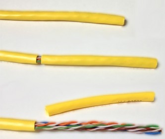
Stripping the outside first
Stripping the outside is easiest done by gently pressing a sharp knife against the plastic, use just enough pressure to carve it, but do cut it not all the way through – we’d like to avoid that we damage the individual wires. With some effort you can pull the plastic off. I usually strip about 5 centimeters or 2 inches, to give me enough room to work with. You could also use a stripping tool for this.
Step 2: Untwisting the wires
Next step is to untangle the individual wires – it’s called “twisted pair” wire for a reason … it’s twisted.
There is no need to strip these, the RJ45 connector (as you might have seen) has tiny gold colored “teeth” that will push straight through the insolation.
Step 3: Sorting the wires
Now comes the hard part – sorting the wires in the proper order and after that cutting them to size. Before doing that, I recommend holding the wire against the RJ45 connector to see how much you will need to cut off (flush – see below for the length).
The wires need to be in a very particular order (same on both ends).
Straight Wire order
| Pin |
Color |
| 1 |
Orange – White |
| 2 |
Orange |
| 3 |
Green – White |
| 4 |
Blue |
| 5 |
Blue – White |
| 6 |
Green |
| 7 |
Brown – White |
| 8 |
Brown |
The pin numbering works as such:
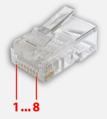
RJ45 Pin numbering
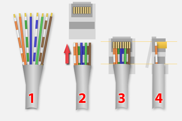
See the steps in the image below;
- Sort the wires in the correct order.
- Keep in mind that the wire has to be inserted into the RJ45 (3 & 4) and cut the individual wires accordingly to size.
- When inserted the outside of the wire should go into the connector until roughly under the end of the clip (keep pushing until it cannot go any further).
- Keep in mind that the individual wires have to go in as far as possible – keep this in mind when cutting them.
For 3 and 4: the yellow lines indicate where the outside of the cable stops, and where the individual wires stop.
Network Cable – Straight
Once inserted properly, keep pressure on it (so the cable doesn’t slide out) and use the crimp tool to “lock” the cable and have the 8 pins puncture the individual cables. I usually squeeze the crimp tool a few times, just to make sure.
Repeat for the other end of the cable.
Step 4: Testing
Most crimp tools can be bought with a cheap cable tested – if you have one of those, then please test the cable before using it.
If you do NOT have a cable tested, consider using a multi-meter to see that the pins are connected right. Pin 1 to Pin 1 etc.
If you don’t have that either: well, inserting (although not recommended) in a router and a computer would give you a good indication … and this type of testing is not without it’s risks! (although; I have never damaged any of my equipment this way)
If you have a 1Gbps network and the router and computer are both capable and set to do so, but both (or one of them) indicates that it’s only a 100Mbps connection, then one of your wires is not making a good contact. Cut the connector off and try again.
Making A Crossed Network Cable
Like I mentioned before; crossed network cables are rarely used. A typically application is to connect 2 network devices without having a network – for example 2 computers or a computer and a NAS or printer. In any of these cases you, of course, will need to set a manual IP address, subnet mask, etc. Keep that in mind! It’s usually a headache to work with.
The entire process is the same, however the wires are crossed, for one of the two cable ends (the other end is done like a normal cable) – we basically connect the TX (send) kabel of one side to the RX (receive) pin of the other side:
Crossed Wire Order
| Pin |
Color |
| 1 |
Green – White |
| 2 |
Green |
| 3 |
Orange – White |
| 4 |
Blue |
| 5 |
Blue – White |
| 6 |
Orange |
| 7 |
Brown – White |
| 8 |
Brown |
More related information can be found on this Wiki page.


Comments
There are 2 comments. You can read them below.
You can post your own comments by using the form below, or reply to existing comments by using the "Reply" button.
Do you know how I can find the answer to how much PSi it takes to cut a Cat6 cable?
scott
Hi Scott,
interesting question and I would have no clue.
I’m guessing, it all would depend on the cable manufacturer and what kind of materials they have used, and how thick the materials would be.
hans