Difference between WS2801, WS2811 and WS2812
Before we start, we should probably identify the differences between the WS2801, WS2811 and WS2812 based strips (also called “strands”).
Most projects and descriptions out there discus these sometimes mixed, and for one who dives into LED strips for the first time, these models numbers might be confusing.
The model numbers WS2801, WS2811 and WS2812 actually refer to different “things”.
The WS2801 and WS2811 are LED driver IC’s (Integrated Circuits).
These IC’s can control up to 3 LEDs, typically Red, Green and Blue. Positioned close together, so you as a viewer will see the mixed color result.
The WS2801 used to be quite popular but the WS2812/WS2811 appears to be taking over the reigns.
The WS2812 however is a WS2811 placed inside a 5050 LED package.
The 5050 LED is a very common 3 LED (Red, Green, Blue) package, in one 5mm x 5mm case.
A WS2812 is the same package but with an additional WS2811 LED driver IC on board.
In the illustration below you’ll see the difference:
On the left a 5050 RGB LED, on the right a WS2812 which combines a 5050 RGB LED with a WS2811 controller.
Note how the layout of the “silver” tracks are almost identical in both images, yet the black (IC) block and the tiny wires are different (right).
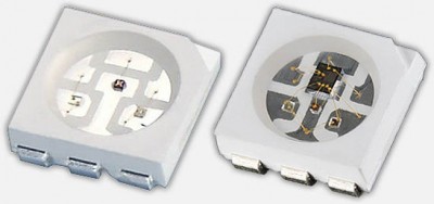
5050 RGB LED (left) and WS2812 (right)
Where the WS2801 strips needed 4 wires, the WS2811/WS2812 strips only needs 3 wires. The WS2801 uses a separate clock line, which can be seen as an advantage, whereas the WS2811/WS2812 does not. The WS2811/WS2812 depends on sending data matching a very tight timing. The advantage of the WS2812 though, is that production of these combo’s in strips is easier and therefor cheaper, and each RGB LED takes much less space on strips.
Your selection here depends on what type of microcontroller you’ll be using and which of these are supported by the application or library you intend to use.
For example, Arduino based projects work fine with any of these, since everything runs real-time.
When using a Raspberry Pi however, using a WS2811/WS2812 can be a little bit more challenging due to the strict timing needs. A Raspberry Pi typically runs Linux, which is not a so-called Real-time Operating System, where intended timing might be disrupted by other background activities.
In my little Arduino project I’ll be using the WS2812.
Specifications
I have made the spec sheets of the 5050 LED, WS2801, WS2811 and WS2812 available as PDF:
– WS2801 Spec Sheet
– WS2811 Spec Sheet
– WS2812 Spec Sheet
– 5050 LED Spec Sheet
These spec sheets can also be downloaded with all 4 PDF’s bundled in a single ZIP file:
Download - WS28xx LED Specification Sheets
Ad Blocking Detected Please consider disabling your ad blocker for our website.
We rely on these ads to be able to run our website.
You can of course support us in other ways (see Support Us on the left).
LED strips Differences
Now that we know the difference between the model numbers, let’s look at a few examples of LED strips.
There are 2 major types of LED strips that support multiple colors: Analog strips and Digital strips.
For our project we want DIGITAL RGB LED stripS … not the analog ones.
ANALOG LED STRIPS
These are NOT the kind of LED strips we use in this project!
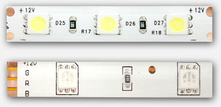
In the illustration below we see first (top) a strip of single color LED’s – typically white, but can be purchased in different colors. The one below that is a multicolor strip (RGB pins are a give away) which allows us to set the color for the entire strip.
On each of these strips you’ll see (from left to right) first the LED as a white block, followed by an SMD resistor as a tiny back block.
The examples below require 12V to operate.

Analog LED strips – Single color (top), Multicolor (bottom)
DIGITAL RGB LED strips
The digital strips are the ones we will use in this project.
In particular: we will use the WS2812 in our project.
The cool part of a digital strip is that you address each LED individually, making very cool effects easy. Obviously the kind we’d like to use in our projects.
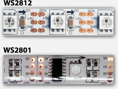
In the illustration below you can see the physical differences between the WS2801 and the WS2811/WS2812 strips.
Unlike the analog strips: Most Digital RGB strips operate on 5 Volts!
Note:
- Not all strips of the same “model”, look the same, but have typically a very similar layout.
- strips can be sold as a white or a black strip (background strip).
- Notice the arrows indicating Data direction.
- WS2801 has 4 pins, where as the WS2811/WS2812 only has 3 pins.
- There are digital strips that look like WS2801/WS2811/WS2812 strip, that are NOT based on any of these LED drivers.
- Strips can be had in waterproof (in plastic “tube”) or for indoor use only.
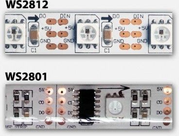
Digital LED strip – WS2812 (top) and WS2801 (bottom)
WS2801 vs WS2812 pins
| PIN |
WS2801 |
WS2812 |
| 5V |
Power (+5V) |
Power (+5V) |
| CI |
Clock signal Input |
N/A |
| CO |
Clock signal Output |
N/A |
| DI |
Data Input |
Data Input |
| DO |
Data Output |
Data Output |
| GND |
Ground or Common |
Ground or Common |
Data Flow
As you can see in the images above:
A 5050 RGB LED + LED Driver IC combo makes a single “unit”.
For the WS2801 this is an IC and a 5050, for the WS2812 this is a single component holding a 5050 LED and WS2811 combined.
These units are chained and each have an input side and an output side. The arrow printed on the strip indicates the data flow direction.
Each output of the previous unit is connected to the input of the following unit, and that’s why we see in the little table INPUT and OUTPUT designated pins.
It’s important to pay attention to the arrow, if you use your strip in the wrong “direction”, it will not work.
Note : Simply connecting +5V and GND will at best flash up your strip for a fraction of a second.
The LEDs need to be “told” to be ON, so without data feed your LEDs will remain OFF.
Time to order a WS2812 RGB LED Strip …
Now that we know the basics and the things to look for, you should be able to order the right strip. Keep in mind that often WS2812 strips are offered as WS2811 strips – different name, same thing. Some sellers mention WS2801 in their product name or advertisement – please make absolutely sure you’re getting the WS2811/WS2812.
Both Amazon and eBay are good resources, and some report positive results with Alibaba … I’ve never ordered from Alibaba, and your milage may vary.
One of my favorite places is AdaFruit, which is not just any random shop, as they provide awesome information when it comes to Arduino projects and the likes.
Making the Arduino WS2812 connection
Now that we have a WS2812 strip, time to hook it up to our Arduino (I used an Arduino UNO for this).
Power
Caution
A strip of LED’s will pull way too much power for your Arduino to handle, so always consider an additional 5V power supply.
Rule of thumb is : each RGB LED unit pulls about 60 mA (3x 20 mA, for Red, Green and Blue).
LED’s, even though they’re called power efficient, do need juice … and for each WS2812 we need up to 60 mA when the 3 LEDs inside are at maximum brightness at 5V.
Power Supply
You can use an external power supply for this purpose and even though my 1 meter strip theoretically needs 3.6 A at max brightness, my little 2A power supply managed to handle it – your milage may vary! (1 meter with 60 LEDs/meter = 60 * 60 mA = 3600 mA = 3.6 A max.)
A switching power supply is often ideal and pretty cheap – you might even have one or the other laying around from your old cellphone, just make sure it’s actually giving you 5 – 6V and not weird voltages like 12V or 16V or even more. Verification with a Voltage meter is recommended.
Batteries
You can consider using batteries, although I’m not a big fan of using them. With batteries please pay attention to the voltage sum.
Consider:
– 3 x Alkaline AA batteries (4.5 V) or
– 4 x NiMH AA rechargeable batteries (4.8 V)
About Amps and such
Like I mentioned before, each LED module takes a max of 60 mA, so you can calculate how many Amps your power source has to provide. Keep in mind that 1000 mA = 1 A.
Your power supply can have overcapacity when it comes to Amps, so if your project needs 3.6 A, and you only have a 10 A power supply, then this will work great.
Keep in mind though that the Voltage must be close to the 5V value. Higher voltages may damage your LEDs.
Connecting Arduino and WS2812 strip
The basic layout of power can be done in 2 ways – with computer or without …
Arduino Connected to your Computer
Commonly, during testing, your Arduino is connected to your computer via a USB cable where the USB cable does not only program the microcontroller but will also provide power for the Arduino.
The DIN (data input) pin of the LED strip goes to Arduino PIN 6 with an optional 470Ω resistor in between.
+5V of the LED strip goes to the +5V of extra power supply.
GND of the LED strip goes to GND of the extra power supply and to the GND of the Arduino.
The USB of the Arduino is connected to your computer.
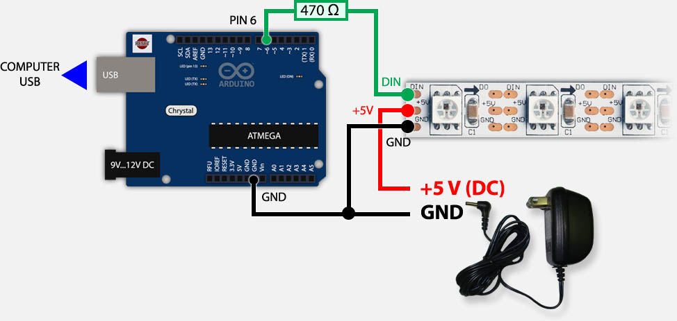
Arduino & WS2812 – USB and External Power
Arduino Not connected to your computer
Once you’ve completed your prototyping, you could still keep using your Arduino for controlling the LED strip.
In that case you’d typically have the Arduino in a very different location, and thus not connected to your computer. In that case the extra power supply for the LEDs could be used to feed the Arduino as well.
The DIN (data input) pin of the LED strip goes to PIN 6 of the Arduino with an optional 470Ω resistor in between.
+5V of the LED strip goes to the +5V of extra power supply and the +5V on your Arduino (or Vin).
GND of the LED strip goes to GND of the extra power supply and to the GND of the Arduino.
Power connected to +5V or Vin?
In the drawing below, you’ll notice that I have used +5V pin for the powersupply.
This works well when you’re using a proper and well regulated powersupply, which I do.
For all correctness, and when using less regulated powersupplies, the Vin pin is recommended.
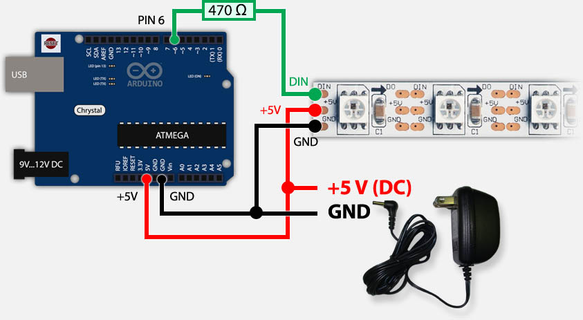
Arduino & WS2812 – Only running on external power supply
Ad Blocking Detected Please consider disabling your ad blocker for our website.
We rely on these ads to be able to run our website.
You can of course support us in other ways (see Support Us on the left).
Programming the Arduino for WS2811/WS2812
Now that we know how to connect the strip to our Arduino, time to get some cool effects going.
We could of course dig into all the timing details of the WS2811/WS2812 but there are already very good libraries out there that do the difficult work for us.
The most used at this moment are FastLED (successor of FastSPI_LED and FastSPI_LED2) and NeoPixel (by AdaFruit). I’ve added some demo videos, and even though it might give you the impression that NeoPixel could be slower, rest assure, it’s not.
Both Libraries are very good and very fast.
Note : If you haven’t already installed the regular Arduino software, please consider looking at “My First Arduino Project” for details and downloads or download links.
AdaFruit NeoPixel
For no obvious reason, I started my first test with NeoPixel by AdaFruit.
The NeoPixel Library for Arduino can be downloaded from Github or through this direct link (zip file) or from Tweaking4All. As usual I HIGHLY recommend getting the files directly from the source as the version on Tweaking4All might be outdated and only serves as a backup.
Download - Adafruit NeoPixel
If you downloaded the Tweaking4All ZIP file, then in the Arduino Software simple choose “Sketch” “Import Library…” “Add Library…” and in the file dialog select the downloaded ZIP file. This will automatically install the library for you (requires Arduino 1.0.5 or newer).
If you however downloaded the official version and this trick did give you an error message, the copy then copy the files from the ZIP archive into a folder called “AdaFruit_NeoPixel” in your Arduino Library directory. More details can be found on the Arduino page concerning Libraries.
- Windows:
My Documents\Arduino\libraries\
- MacOS X:
~/Documents/Arduino/libraries/
- Linux:
~/Documents/Arduino/libraries/
After installing the Library, close and restart the Arduino software so that the examples are not visible in the menu.
The first example I ran was of course striptest to see if my LED strips worked alright – choose from the menu “File” “Examples” “AdaFruit_NeoPixel” “striptest“.
Before compiling and uploading the sketch to your Arduino, first verify some basic settings in the code.
– line 3 : make sure #define PIN 6 is actually matching the pin number you’ve used on your Arduino
– line 12 : make sure the first parameter in Adafruit_NeoPixel(60, ... matches the number of LED’s in your strip (here: 60).
If you used the wiring schematics shown earlier then PIN 6 would be the right pin. Click the “Upload” button, wait a few seconds and see the magic at work.
Here a short video of the NeoPixel demo – I didn’t do too much effort as you can see, but it gives you an idea ….
1
2
3
4
5
6
7
8
9
10
11
12
13
14
| #include <Adafruit_NeoPixel.h>
#define PIN 6
// Parameter 1 = number of pixels in strip
// Parameter 2 = pin number (most are valid)
// Parameter 3 = pixel type flags, add together as needed:
// NEO_KHZ800 800 KHz bitstream (most NeoPixel products w/WS2812 LEDs)
// NEO_KHZ400 400 KHz (classic 'v1' (not v2) FLORA pixels, WS2811 drivers)
// NEO_GRB Pixels are wired for GRB bitstream (most NeoPixel products)
// NEO_RGB Pixels are wired for RGB bitstream (v1 FLORA pixels, not v2)
Adafruit_NeoPixel strip = Adafruit_NeoPixel(60, PIN, NEO_GRB + NEO_KHZ800);
... |
I highly recommend snooping through the code of this example, make some changes, see what happens.
The full code can be found below.
Pay attention to these functions:
1
2
3
4
5
6
| strip.begin(); // initialize strip
strip.show(); // Update all LEDs (= turn OFF, since none of them have been set yet!)
...
c = strip.Color(255, 0, 0); // define the variable c as RED (R,G,B)
strip.setPixelColor(10, c); // set LED 10 to the color in variable c (red)
strip.show(); // Update all LEDs (= make LED 10 red) |
It’s worth playing with for a bit to get familiar with how things are being called.
Note : To switch a LED off use the color BLACK (strip.Color(0,0,0)).
1
2
3
4
5
6
7
8
9
10
11
12
13
14
15
16
17
18
19
20
21
22
23
24
25
26
27
28
29
30
31
32
33
34
35
36
37
38
39
40
41
42
43
44
45
46
47
48
49
50
51
52
53
54
55
56
57
58
59
60
61
62
63
64
65
66
67
68
69
70
71
72
73
74
75
76
77
78
79
80
81
82
83
84
85
86
87
88
89
90
91
92
93
94
95
96
97
98
99
100
101
102
103
104
105
106
107
108
109
110
111
112
113
114
115
116
117
| #include <Adafruit_NeoPixel.h>
#define PIN 6
// Parameter 1 = number of pixels in strip
// Parameter 2 = pin number (most are valid)
// Parameter 3 = pixel type flags, add together as needed:
// NEO_KHZ800 800 KHz bitstream (most NeoPixel products w/WS2812 LEDs)
// NEO_KHZ400 400 KHz (classic 'v1' (not v2) FLORA pixels, WS2811 drivers)
// NEO_GRB Pixels are wired for GRB bitstream (most NeoPixel products)
// NEO_RGB Pixels are wired for RGB bitstream (v1 FLORA pixels, not v2)
Adafruit_NeoPixel strip = Adafruit_NeoPixel(60, PIN, NEO_GRB + NEO_KHZ800);
void setup() {
strip.begin();
strip.show(); // Initialize all pixels to 'off'
}
void loop() {
// Some example procedures showing how to display to the pixels:
colorWipe(strip.Color(255, 0, 0), 50); // Red
colorWipe(strip.Color(0, 255, 0), 50); // Green
colorWipe(strip.Color(0, 0, 255), 50); // Blue
// Send a theater pixel chase in...
theaterChase(strip.Color(127, 127, 127), 50); // White
theaterChase(strip.Color(127, 0, 0), 50); // Red
theaterChase(strip.Color( 0, 0, 127), 50); // Blue
rainbow(20);
rainbowCycle(20);
theaterChaseRainbow(50);
}
// Fill the dots one after the other with a color
void colorWipe(uint32_t c, uint8_t wait) {
for(uint16_t i=0; i<strip.numPixels(); i++) {
strip.setPixelColor(i, c);
strip.show();
delay(wait);
}
}
void rainbow(uint8_t wait) {
uint16_t i, j;
for(j=0; j<256; j++) {
for(i=0; i<strip.numPixels(); i++) {
strip.setPixelColor(i, Wheel((i+j) & 255));
}
strip.show();
delay(wait);
}
}
// Slightly different, this makes the rainbow equally distributed throughout
void rainbowCycle(uint8_t wait) {
uint16_t i, j;
for(j=0; j<256*5; j++) { // 5 cycles of all colors on wheel
for(i=0; i< strip.numPixels(); i++) {
strip.setPixelColor(i, Wheel(((i * 256 / strip.numPixels()) + j) & 255));
}
strip.show();
delay(wait);
}
}
//Theatre-style crawling lights.
void theaterChase(uint32_t c, uint8_t wait) {
for (int j=0; j<10; j++) { //do 10 cycles of chasing
for (int q=0; q < 3; q++) {
for (int i=0; i < strip.numPixels(); i=i+3) {
strip.setPixelColor(i+q, c); //turn every third pixel on
}
strip.show();
delay(wait);
for (int i=0; i < strip.numPixels(); i=i+3) {
strip.setPixelColor(i+q, 0); //turn every third pixel off
}
}
}
}
//Theatre-style crawling lights with rainbow effect
void theaterChaseRainbow(uint8_t wait) {
for (int j=0; j < 256; j++) { // cycle all 256 colors in the wheel
for (int q=0; q < 3; q++) {
for (int i=0; i < strip.numPixels(); i=i+3) {
strip.setPixelColor(i+q, Wheel( (i+j) % 255)); //turn every third pixel on
}
strip.show();
delay(wait);
for (int i=0; i < strip.numPixels(); i=i+3) {
strip.setPixelColor(i+q, 0); //turn every third pixel off
}
}
}
}
// Input a value 0 to 255 to get a color value.
// The colours are a transition r - g - b - back to r.
uint32_t Wheel(byte WheelPos) {
if(WheelPos < 85) {
return strip.Color(WheelPos * 3, 255 - WheelPos * 3, 0);
} else if(WheelPos < 170) {
WheelPos -= 85;
return strip.Color(255 - WheelPos * 3, 0, WheelPos * 3);
} else {
WheelPos -= 170;
return strip.Color(0, WheelPos * 3, 255 - WheelPos * 3);
}
} |
FastLED (FastSPI_LED)
FastLED is the successor of FastSPI_LED and FastSPI_LED2. According to it’s maintainer(s) the name changed to FastLED since it’s no longer just focussing in SPI LED strips like the one we’re using in our project (WS2811/WS2812). Some older chipsets have been dropped so for older LED strips (non WS2801-WS2812) might want to resort to the older FastSPI_LED2 library.
To download the library you can either click the “Download ZIP” button on the FastLED GitHub page, click this link to directly download the ZIP file, or download a snapshot from Tweaking4All. As usual: we highly recommend getting the files from the source … the Tweaking4All version is only here as a backup and is most likely outdated.
If you downloaded the Tweaking4All ZIP file, then in the Arduino Software simple choose “Sketch” “Import Library…” “Add Library…” and in the file dialog select the downloaded ZIP file. This will automatically install the library for you (requires Arduino 1.0.5 or newer).
If you however downloaded the official version and this trick did give you an error message, then copy the files from the ZIP archive into a folder called “FastLED” in your Arduino Library directory. More details can be found on the Arduino page concerning Libraries.
- Windows:
My Documents\Arduino\libraries\
- MacOS X:
~/Documents/Arduino/libraries/
- Linux:
~/Documents/Arduino/libraries/
After installing the Library, close and restart the Arduino software so that the examples are not visible in the menu.
The first example I tried was “testleds” only to find out that it was a left over from FastSPI_LED and did not run. So I updated the code to work with FastLED, you can copy and paste it into the Arduino editor.
Make sure to verify the following lines:
– line 3: make sure you set the number of LEDs right in #define NUM_LEDS 60
– line 8: make sure the correct PIN is set in #define PIN 6
Here you will see that the NeoPixel demo was maybe cooler, but the code for FastLED appears shorter. In the end both Libraries are solid, so pick which you prefer.
As with the NeoPixel code – I highly recommend snooping through the code, modify a few things and see what it does and such. It’s actually fun to do.
Here a video of what the demo does – I didn’t take too much effort to do a perfect video, and I didn’t record the entire test, heck I didn’t even take the LED strip out of the zip-lock bag … 
Addressing LEDs with FastLED works a little different but one could see it as much easier … personal preference … for a list of pre-defined colors see the list after the source code.
Note : to switch a LED Off, set the color to Black as such, before calling the show() function: leds[10] = CRGB::Black; .
1
2
3
4
5
6
7
8
9
| leds[10] = CRGB::Red; // Set LED 10 to red
FastLED.show(); // Show changes
...
leds[10].r = 255; // set red for LED 10 (Color = Red + Green + Blue)
leds[10].g = 125; // set green for LED 10
leds[10].b = 0; // set blue for LED 10
FastLED.show(); // Show changes |
1
2
3
4
5
6
7
8
9
10
11
12
13
14
15
16
17
18
19
20
21
22
23
24
25
26
27
28
29
30
31
32
33
34
35
36
37
38
39
40
41
42
43
44
45
46
47
48
49
50
51
52
53
54
55
56
57
58
59
60
61
62
63
64
65
66
67
68
69
70
71
72
73
74
75
76
77
78
79
| #include "FastLED.h"
// Number of RGB LEDs in the strand
#define NUM_LEDS 60
// Define the array of leds
CRGB leds[NUM_LEDS];
// Arduino pin used for Data
#define PIN 6
void setup()
{
FastLED.addLeds<NEOPIXEL, PIN, RGB>(leds, NUM_LEDS);
}
void loop() {
// one at a time
for(int j = 0; j < 3; j++) {
for(int i = 0 ; i < NUM_LEDS; i++ ) {
memset(leds, 0, NUM_LEDS * 3);
switch(j) {
case 0: leds[i].r = 255; break;
case 1: leds[i].g = 255; break;
case 2: leds[i].b = 255; break;
}
FastLED.show();
delay(10);
}
}
// growing/receeding bars
for(int j = 0; j < 3; j++) {
memset(leds, 0, NUM_LEDS * 3);
for(int i = 0 ; i < NUM_LEDS; i++ ) {
switch(j) {
case 0: leds[i].r = 255; break;
case 1: leds[i].g = 255; break;
case 2: leds[i].b = 255; break;
}
FastLED.show();
delay(10);
}
for(int i = NUM_LEDS-1 ; i >= 0; i-- ) {
switch(j) {
case 0: leds[i].r = 0; break;
case 1: leds[i].g = 0; break;
case 2: leds[i].b = 0; break;
}
FastSPI_LED.show();
delay(1);
}
}
// Fade in/fade out
for(int j = 0; j < 3; j++ ) {
memset(leds, 0, NUM_LEDS * 3);
for(int k = 0; k < 256; k++) {
for(int i = 0; i < NUM_LEDS; i++ ) {
switch(j) {
case 0: leds[i].r = k; break;
case 1: leds[i].g = k; break;
case 2: leds[i].b = k; break;
}
}
FastLED.show();
delay(3);
}
for(int k = 255; k >= 0; k--) {
for(int i = 0; i < NUM_LEDS; i++ ) {
switch(j) {
case 0: leds[i].r = k; break;
case 1: leds[i].g = k; break;
case 2: leds[i].b = k; break;
}
}
FastLED.show();
delay(3);
}
}
} |
Predefined colors in FastLED:
AliceBlue = 0xF0F8FF
Amethyst = 0x9966CC
AntiqueWhite = 0xFAEBD7
Aqua = 0x00FFFF
Aquamarine = 0x7FFFD4
Azure = 0xF0FFFF
Beige = 0xF5F5DC
Bisque = 0xFFE4C4
Black = 0x000000
BlanchedAlmond = 0xFFEBCD
Blue = 0x0000FF
BlueViolet = 0x8A2BE2
Brown = 0xA52A2A
BurlyWood = 0xDEB887
CadetBlue = 0x5F9EA0
Chartreuse = 0x7FFF00
Chocolate = 0xD2691E
Coral = 0xFF7F50
CornflowerBlue = 0x6495ED
Cornsilk = 0xFFF8DC
Crimson = 0xDC143C
Cyan = 0x00FFFF
DarkBlue = 0x00008B
DarkCyan = 0x008B8B
DarkGoldenrod = 0xB8860B
DarkGray = 0xA9A9A9
DarkGreen = 0x006400
DarkKhaki = 0xBDB76B
DarkMagenta = 0x8B008B
DarkOliveGreen = 0x556B2F
DarkOrange = 0xFF8C00
DarkOrchid = 0x9932CC
DarkRed = 0x8B0000
DarkSalmon = 0xE9967A
DarkSeaGreen = 0x8FBC8F
DarkSlateBlue = 0x483D8B
DarkSlateGray = 0x2F4F4F
DarkTurquoise = 0x00CED1
DarkViolet = 0x9400D3
DeepPink = 0xFF1493
DeepSkyBlue = 0x00BFFF
DimGray = 0x696969
DodgerBlue = 0x1E90FF
FireBrick = 0xB22222
FloralWhite = 0xFFFAF0
ForestGreen = 0x228B22
Fuchsia = 0xFF00FF
Gainsboro = 0xDCDCDC
GhostWhite = 0xF8F8FF
Gold = 0xFFD700
Goldenrod = 0xDAA520
Gray = 0x808080
Green = 0x008000
GreenYellow = 0xADFF2F
Honeydew = 0xF0FFF0
HotPink = 0xFF69B4
IndianRed = 0xCD5C5C
Indigo = 0x4B0082
Ivory = 0xFFFFF0
Khaki = 0xF0E68C
Lavender = 0xE6E6FA
LavenderBlush = 0xFFF0F5
LawnGreen = 0x7CFC00
LemonChiffon = 0xFFFACD
LightBlue = 0xADD8E6
LightCoral = 0xF08080
LightCyan = 0xE0FFFF
LightGoldenrodYellow = 0xFAFAD2
LightGreen = 0x90EE90
LightGrey = 0xD3D3D3
LightPink = 0xFFB6C1
LightSalmon = 0xFFA07A
LightSeaGreen = 0x20B2AA
LightSkyBlue = 0x87CEFA
LightSlateGray = 0x778899
LightSteelBlue = 0xB0C4DE
LightYellow = 0xFFFFE0
Lime = 0x00FF00
LimeGreen = 0x32CD32
Linen = 0xFAF0E6
Magenta = 0xFF00FF
Maroon = 0x800000
MediumAquamarine = 0x66CDAA
MediumBlue = 0x0000CD
MediumOrchid = 0xBA55D3
MediumPurple = 0x9370DB
MediumSeaGreen = 0x3CB371
MediumSlateBlue = 0x7B68EE
MediumSpringGreen = 0x00FA9A
MediumTurquoise = 0x48D1CC
MediumVioletRed = 0xC71585
MidnightBlue = 0x191970
MintCream = 0xF5FFFA
MistyRose = 0xFFE4E1
Moccasin = 0xFFE4B5
NavajoWhite = 0xFFDEAD
Navy = 0x000080
OldLace = 0xFDF5E6
Olive = 0x808000
OliveDrab = 0x6B8E23
Orange = 0xFFA500
OrangeRed = 0xFF4500
Orchid = 0xDA70D6
PaleGoldenrod = 0xEEE8AA
PaleGreen = 0x98FB98
PaleTurquoise = 0xAFEEEE
PaleVioletRed = 0xDB7093
PapayaWhip = 0xFFEFD5
PeachPuff = 0xFFDAB9
Peru = 0xCD853F
Pink = 0xFFC0CB
Plaid = 0xCC5533
Plum = 0xDDA0DD
PowderBlue = 0xB0E0E6
Purple = 0x800080
Red = 0xFF0000
RosyBrown = 0xBC8F8F
RoyalBlue = 0x4169E1
SaddleBrown = 0x8B4513
Salmon = 0xFA8072
SandyBrown = 0xF4A460
SeaGreen = 0x2E8B57
Seashell = 0xFFF5EE
Sienna = 0xA0522D
Silver = 0xC0C0C0
SkyBlue = 0x87CEEB
SlateBlue = 0x6A5ACD
SlateGray = 0x708090
Snow = 0xFFFAFA
SpringGreen = 0x00FF7F
SteelBlue = 0x4682B4
Tan = 0xD2B48C
Teal = 0x008080
Thistle = 0xD8BFD8
Tomato = 0xFF6347
Turquoise = 0x40E0D0
Violet = 0xEE82EE
Wheat = 0xF5DEB3
White = 0xFFFFFF
WhiteSmoke = 0xF5F5F5
Yellow = 0xFFFF00
YellowGreen = 0x9ACD32


Comments
There are 516 comments. You can read them below.
You can post your own comments by using the form below, or reply to existing comments by using the "Reply" button.
Hi,
Great article. A lot of help.
Question … what it the purpose of the
optional 470 resistor?
Thanks
Thomas
Thanks Thomas!
ADAFruit and others recommend this to “dampen” spikes on the data pin … in my [limited] experience with electronics, I would have grabbed a capacitor for that, but they recommend a resistor.
In my experience: the setup works just fine with the resistor – I have yet to blow up my Arduino …
…
hans
The reason you use a resistor as Lady Ada reccomends on the Neopixel is as follows: The resistor drops the input voltage of 5 volts. (I know you know that). A caacitor always blocks a DC voltage so placing in series on the +5 volts would block the +5DC. But-were you to take that same capacitor across the 5 voltage (from the+ 5 volt side to the ground side) it filters any AC voltage riding on the DC.
Put another way-capacitors block DC but allow some AC so static(noise, transients) riding on a DC line are shunted (siphoned off) the DC line. The higher the frequency the more of that AC will siphon; thus smoothing the DC on the input side.
And-as to why DC might have have AC riding on it to begin with-it most likely would come from a plug in(AC) power supply that outputs DC- that is leaky(inferior design, cheap or old componen components). Hope that helps.
Cappy Anderson
Thanks Cappy for the clear explanation, exactly as I intended it – just in better detail explaining the difference between resistor and capacitor in this application.
hans
I am sorry Cappy but that explanation is wrong in all aspects.
First of all the resistor does not “drop” any voltage. Resistors only drop voltage according to how much current is flowing and in this case when the input impedance of the WS2812 is very high there is sod all current flowing so there is sod all voltage drop. What is happening is that there is a transmission line situation, especially where the LED strip is some distance from the driving source. So a rising edge on the driver hits the mismatched impedance at the LED and reflects the signal back, this gets reflected back from the low impedance of the driver because again there is a miss match and you get a standing wave on the line. The resistor is there to absorb the power in this standing wave and damp it down.
Now as to the question of why not use a capacitor. If you used a series capacitor then driving one end of a capacitor at 0 to 5V would produce a signal of -5 to +5V on the other end. The -5V would kill the LED and would do nothing to suppress the standing wave. If you put the capacitor in parallel, that is from the input of the LED to ground then you degrade the rise time of the signal and so it would not work.
Grumpy_Mike
Thanks Grumpy Mike for the clarification, this way we learn something new every day …
…
hans
Hi Grumpy Mike,
Nice explanation, but I don’t see how a 470 ohm resistor in series with a high impedance input will absorb anything. Surely for that to work the resistor needs to be to ground.
Marshy
Marshy
Not too sure how much about electronics you understand. I have only been doing it for 50 years now so I am sure I still don’t understand everything but I suspect it is more than you.
but I don’t see how a 470 ohm resistor in series with a high impedance
input will absorb anything.
Have you ever come across the concept of a standing wave? The current flow is not through the high impedance input, it bounces off the high impedance input back along the line. Then it hits the impedance discontinuity at the Arduino and bounces back. If there is nothing to absorb the energy then this bouncing backwards and forwards sets up a standing wave that can interfere with any future signal. It is all standard transmission line theory. How much of that do you know?
Surely for that to work the resistor needs
to be to ground
I think that comment shows you know very little. All you need to do is to have current flowing through a resistor for it to absorb power. Think of using a long wire with a non negligible amount of resistance, no connection to ground but there is a volts drop at the end of the line and it absorbs power.
Grumpy_Mike
The resistor isn’t needed to protect the Arduino from standing waves or we would see them used quite often on outputs plus the Arduino output is capable of handling currents up to 40ma and any reflected wave would be so small it would be almost impossible to measure. The real reason for the resistor is that many have had the first LED in a string fail which can easily happen when the LED string and Arduino are powered from seperate power supplies and either the Arduino supply is turned on first or it powers up a bit quicker than the LED power supply. When this happens and the Arduino output (which can supply up to 40ma safely and even much more current into a low impedance load) is HIGH, 5V will flow into the input of the first LED and end up trying to power the LED string which will result in more current flow than the input can withstand and distroy the input. Yes, the input is normally a high impedance input, but only when the LED is powered. Without a schematic of the LED circuit is hard to say exactely how 5V on the input reaches the 5V input and tries to power the LED, but it’s common practice to use diodes on high impedance inputs to protect the input and I’m guessing there’s a diode from the input to the 5V rail. These diodes are usually rated for no more than 10ma so would quickly be distroyed by 5v from an Arduino which would then result in the input circuitry also being distroyed. Anyway, A 470 ohm resistor will limit the current to no more than 10ma and allow the input protection diodes to do their job and not affect the signal when the LED is powered and the input becomes a much higher impedance.
Barry
Opinion seems to be divided about the necessity of a resistor and/or a capacitor when hooking up Neopixel strips.
I come down on the side of using both, probably because the first tutorial recommended both – Adafruit in particular.
What I’ve not seen addressed is what to do when injecting more power downline on connected strips.
Here’s my take on it, comments welcome.
circuitdriver
Power injection does not affect data. Data is regenerated within each LED. However the resistance of the copper over distance causes voltage drop making the downstream LEDs dimmer. This is why you need to add power downstream.
I have a string of 128 ws2812 LEDs around a bar. To make sure there was the same brightness at each end of the strip I fed DC through 18awg wire to both ends of the strip.
As GrumpyMike said the first resistor is to damp any standing waves caused by power reflection from damaging your driver device.
Dannlh
See reply #9 on this thread https://forum.arduino.cc/index.php?topic=489310.0 for the picture I took with and without a resistor. See any difference? Because I do.
The spikes on the signal could damage your Arduino or your LED strip because they are greater than the power rails.
So when Barry said “The resistor isn’t needed to protect the Arduino from standing waves or
we would see them used quite often on outputs plus the Arduino output is
capable of handling currents up to 40ma and any reflected wave would be
so small it would be almost impossible to measure.”
He was wrong, it is nothing to do with the current it is all about the voltage. The rest of his post is complete nonsense.
Grumpy_Mike
Hello-
I just wanted to tell you how much I enjoyed this write up ! Why? The graphics are top notch but now I’ll say what impressed me s much. You style of writing is without a doubt-one of the best I have read. You writing is lucid, informative, succinct, and explicit. This is-in my opinion-something very rare, especially as it relates to informing someone about a technical subject! Any fool can complicate a subject! Rare is the person who can take a fairly complex subject, and make it simple to understand.
Well done!!
Cappy Anderson
Hi Cappy,
I’m actually amazed by your comment, including goose bumps – thank you very much for this very nice compliment . I’m glad to hear that you like my way of writing, although I do not consider myself a writer.
Thanks for leaving such a nice comment, it makes writing more articles more than worth it.
hans
Well said, it has became rare to come across someone who can use the English language correctly.
Poppy Ann
Thanks Poppy Ann!
I really appreciate hearing this, and it does mean I’m getting close to my goal to reach everybody (always disliked it when folks write in a way so only their peers may understand it).
Language should never be a barrier when trying to access information or learn something, even if the reader is not an expert.
If only I would make less typos …
…
hans
Adafruit_NeoPixel şerit = Adafruit_NeoPixel (60, PIN, NEO_GRB + NEO_KHZ800);
Benim ilk uno lütfen çok acil 1 mega-2 nano-LED çalışmıyor ws2811
canufuk
very urgent please my first uno 1 mega-2 nano-LEDs are not working ws2811
canufuk
HI neon tube can working ws2811. but ws2811 just DC12V. not DC24V, if DC24V.willl be UCS1903
WItop-tech
I have no idea what you’re asking.
Please post your question either in English, Dutch or German.
“Very urgent” and no description of the problem makes it hard to trouble shoot. Please provide more detailed information.
hans
salute me
1uno
2 nano
1meg to
does not work in there, but none
ws2811 LED strips and mushrooms in 2811
please help
Adafruit_NeoPixel strip = Adafruit_NeoPixel(60, PIN, NEO_GRB + NEO_KHZ800);
Thank you in advance stays here
canufuk
Hi Canufuk,
I understand that you have an Arduino Uno, a Nano and a MEGA.
You’re using WS2811 LEDs and they don’t work? Not sure what Mushroom means?
Do they stay OFF, show the wrong colors, or only a few work?
hans
i have the same problem with WS2811
they blink once and then stay off
Martin Hansen
Thanks for this complete article, very usefull !
Especially the digital led type sumary !
;)
Showtime
Thanks Showtime
I very much appreciate the positive feedback.
hans
Were you ever able to get these WS2812 strips working with an ambilight setup?
Dave
Hi Dave,
I haven’t had time yet to start that part of the project and I ran into one problem being that one of the strips I ordered was failing.
However … I do plan to start this project! I’ll post a comment here once I’ve completed the project (I’ll be posting an article about it as well).
hans
Great! Do you have any tips on where one would start looking into this themselves? I would say I’m an intermediate programmer, but my knowledge of the ambilight software and how it should work is minimal. I have a few of the WS2812 strips coming in tomorrow and I’m a bit anxious to start doing something with them.
Thanks Hans
DAVE
Well, my first step was getting familiar with Arduino and WS2812 LED strips, just playing with it to understand how it all works. For Ambilight/Boblight you’ll be able to find plenty links (Google). As far as I understand: the Arduino will be hooked to an XBMC box, and a XBMC plugin will steer it.
What I don’t like about that articular setup is that it the Ambilight will only work when playing media on your XBMC box. I’d rather have it work all the time … I have done a lot of reading on the matter and short from breaking open my TV, doing this is not as easy as when using it for XBMC only.
After playing with Arduino and the LED strips, the next step would be planning how to mount it on your TV. I have seen people using double sided tape but that’s not for me – I hate finding glue residue on my TV in case I remove it. Making a bracket would be the way to go utilizing the VESA mount on your TV. Or at least think about how you’d like to do it.
Next step would be a test setup: XBMC -> Arduino -> LED strips. See how it works before mounting anything on your TV.
This is what I found at GitHub, but there are plenty more sources/articles (look for WS2811/WS2812).
hans
Luckily for me 99% of my media comes from my XBMC box. This gives me plenty to go off though. I will definitely be making some kind of bracket. I have some analog LED strips on the back of my TV now that I occasionally use and while the glue from the tape didn’t leave any residue that is because it wasn’t very strong and they tend to fall occasionally. I guess the best thing to do is just dive in and see what I can do. Thanks again.
DAVE
Cool! Maybe we should keep each other posted about our progress …
…
I hope to start by the end of the week …
hans
I’m not entirely optimistic about making much useful progress, but I will definitely keep you posted if I do.
DAVE
No worries … I’ll keep you posted!
I’ll first have to do some shopping for something to create a bracket.
hans
So I got my WS2812 LED strips yesterday and after many hours of playing around with the different colors and patterns and how the LED addressing worked I was able to kind of get something working. I started with the arduino code from here:
http://shredrexx.wordpress.com/2013/04/19/ambilight-variation-using-radio-shack-rgb-strip/
and the processing code from here:
https://github.com/adafruit/Adalight/blob/master/Processing/Adalight/Adalight.pde
I don’t have my code with me, but I was able to get the whole strip to light up the proper color based on the display. There was a huge delay in matching the color and it showed some other colors occasionally which I think had to do with the way that I was reading the serial input. I think my biggest problem now is that I’m not sure how to assign segments of the LED strip to correspond with a matching section on the screen. It also seems like the time it takes for the strip to change to the proper color takes a while, but this most likely has to do with the way that I address the LEDs with the serial input.
DAVE
I’m not able to look into this right now (hopefully soon!) but as far as I recall you’ll need to configure the boblight plugin for XBMC to talk “properly” to your Arduino.
On this (Russian) page, a guy used a WS2812 like that: http://habrahabr.ru/post/200200/ (not sure if Google Translate works this way, but here is the translated link). I also found some Arduino code at PasteBin for this purpose.
I’m sorry I haven’t gotten to this little project yet – I’m trying to finish up another project before starting a new one.
hans
No rush, I like trying to figure this stuff out on my own as best I can. Great find with the Russian site, after a quick read through it makes it look easier than I thought.
DAVE
I was thinking the same thing after reading the Russian site … looks like I finished my little project, so I hope to give BobLight a start tomorrow …
…
hans
So I finally got everything working today. I used the arduino code from that Russian site and I more or less followed the guide found here:
http://forum.xbmc.org/showthread.php?tid=145908
There is also a link in there for a boblight.conf file generator that worked fairly well. The one thing that took me way too long to realize was that I had to change the prefixes found in the WaitForPrefix function to match my prefixes in boblight.conf file. I have a little more tweaking to do to get everything how I want and then I will mount them.
You mentioned that one of your strips was failing. What was the problem with it? I ordered 4 meters and there seems to be almost a one meter section that is a little touchy. If I press on the LED directly before the bad part it works fine. I’m not sure what to do about it I don’t really want to have to send them all back, but I imagine it may work for now and then give me problems down the road.
Dave
Awesome Dave! Glad you got it to work!
I’m still stuck in the “build a bracket” phase. My TV is 80″, so I need a rather big bracket and I haven’t been able to find materials for that (looking at local stores). I’ve been thinking about using aluminium square tubes or maybe something useful I can find in the local hardware store (my initial ideal was using a sheet of plexiglass with openings cut into it – until I found out how expensive plexiglass can be).
One of the strips I have fails after LED number 20, probably a minor issue (poor connection or dead chip), which I’ve figured a purpose for already. At the bottom of my TV, I wouldn’t need the full width anyway, so I could cut this strip in 2 parts. Sounds like you’re running in a similar issue. Although mine came in 5x 1 meter strips. You can could the strips, as long as you reconnect +5V, GND and Din from one strip to another.
Maybe these strips are designed to be 1 meter? Can you see anything that suggest this?
I did see at AdaFruit that they recommend having power fed to the strips in between (as shown in this article or this picture) – unlike the Russian website that suggests using thick wires between the strips.
hans
I think I’m just gonna cut the bad LED out and resolder the connection. I don’t know why I didn’t think of that, but my strip came as one long strip rather than individual strips.
I used blue half inch pvc (the kind used for water lines) for a bracket and used zip ties to connect the strips to it. I liked it because it allowed me to easily adjust the direction that the strips were pointing so I could get the optimal light reflection off of the wall.
I tried putting power to both ends of the strip, but I didn’t really notice a difference so I’m just using one end.
Dave
What kind of XBMC setup are you running? (ie. Windows, Mac, Linux, OpenElec, RaspBMC, etc)
I read in an article about a possible delay issue with OpenElec, so I was just wondering if I’d had to switch to another XBMC distro (using OpenElec right now).
hans
I’m using windows. I’ve only run OpenElec on my Raspberry pi which is not my main HTPC so I’m not sure about the delay.
Dave
Well, I made some progress … I did build a nice aluminium frame (used countertop trims/edging), and installed the LED strips.
I used the test program (above) to make sure all LEDs worked OK, and found only one that was dead.
I fixed that by bypassing the LED (Shortcut Din and Dout of the LED). So the above demo works great.
Now I’m kind-a stuck in getting XBMC to talk to the Arduino … did you use the Sketch of the Russian website?
(I did recreate the config file with a script I found here)
I’m sure the Sketch of AdaFruit is not going to work, since it expects a WS2801 instead of the WS2811/WS2812.
hans
Well, unfortunately for me my strips started failing shortly after actually taking them off of the reel after I had finished all testing.
Are you using the boblight addon in XBMC and the boblightd script? The only thing I changed in the sketch from that site were the number of LEDs, the speed, and the prefixes to watch for in the WaitForPrefix function. I got the prefixes for that out of my boblight.conf file that I got from a config file generator. After that I just made sure that the baud rate and the COM port were consistent through everything involved.
Dave
Thanks Dave for replying this quick. Bummer your LEDs are crapping out though …
…
My were delivered in 1 Meter strands so I had some serious soldering to do to complete the frame.
I am using the boblightd plugin for XBMC, and had a script create my config file. I changed the speed (boblightd and Arduino Sketch to 38400), and the number of LEDs. I did try using the $55 $AA initiation string in the config file, but this did not work. So you used the ones the config generate created? How did you add this in the code?
hans
Yeah, the good thing is they will be replacing them. Reading through the support forums it seems like they’ve been having some unknown problems with these strips lately.
In the [device] section of the config file I have this line:
prefix 41 64 61 00 D5 80
I replaced the 0x55 and 0xAA from the sketch and used 0x41 and 0x64 instead. As much as I’ve tried I can’t really find too much information about boblight. One issue I’m still trying to deal with is that when I start boblight, either the first or the last LED in my string is purple.
Dave
OK, got mine up and running … it’s awesome!
I did however use the Sketch from NeoBob which uses NeoPixel, and performs very well. Might be worth a try.
So far I had only one LED fail, which I initially shorted to bypass, but I had a few LEDs left over so I did cut the bad LED out of the strip and replaced it with a working LED.
Next issue: making a proper config file, but I’ll keep that one for tonight so I can actually see the color differences well .
.
hans
That’s great! I will definitely have to try that NeoBob sketch. I’m hoping that will solve my problem with the first or last two LEDs lighting up purple.
The config file still confuses me a bit. I think I need to find a better script to create mine because the one I was using is a little difficult to use.
dave
So I got my new lights today and everything is working great on the hardware side, but the software side definitely needs some tweaking. The NeoBob sketch is working much better than the sketch from the Russian site with a few caveats. The last two LEDs are still always turned on to purple or blue. Have you experienced this at all?? I also feel like the colors with the Russian sketch were more true to the screen whereas the NeoBob sketch seems a bit off. The blacks are also not represented very well with either sketch. I’ve spent a ton of time trying to change the different values for boblight and the sketch and have not been able to get everything dialed in. Have you had any more luck with this??
Dave
Hi Dave!
Last two LEDs on or “frozen” in a color … I’ve seen that in two scenario’s:
– When the number of lights and channels (=lights*3) do not match up
– When your power supply is not keeping up (set brightness lower if you can)
As for the colors: Yeah, I noticed that the colors aren’t always that “true”, but I haven’t spent time on that part yet. (still working on it).
I’ve been toying with the LED positions and got tired of doing this with scripts so I decided to write my own program
I would like to focus, once the program is done, on what the NeoBob Sketch is doing with the colors (vs. the Russian Sketch).
If you’re saying that there is a difference then we might have to take a peek there …
hans
Oh and if you’d like to see “untrue” colors, and lag, then look at the video I recorded.
Please never mind the music: I only used the video clip of a laser show I found on YouTube, just to see how “fast” things are.
hans
Made some really good progress today ….
1) Finished the application to create a config file and it works GREAT …
…
2) I also created a test video (to verify my App) which also works great! (planning on releasing a Windows, MacOS X and Linux version)
Bot should be available soon, if you’d like I can email you the test video (it’s about 1Mb). No need to let me know your email address, I have it, but I just don’t want to sent unsolicited emails.
Tonight I’ll be working on speed (get rid of the lag) and I’ll take a look at the Sketches of NeoBob and the Russian website – see if I can get color better.
hans
I think I finally got my config file just how I want it, but I wouldn’t mind trying out your app. The one I was using didn’t have a lot of options and I had to manually change some settings in the device section.
Per your advice, I was able to get rid of the pixels that were stuck on by matching up the number of channels and the number of LEDs.
My colors seem to have gotten a lot better since I changed the hscan and vscan to only 5%. The only thing that I am really having trouble with is blacks. Whenever there are dark areas it seems like it is still able to pick up something and it lights it up whatever color it thinks is there even if it is a very small amount.
Dave
Another tip:
I increased the baudrate (460800) and added priority (99) to the [device] section in the config file, which seems to reduce the lag – but to be honest at this point I’m not sure anymore how to measure the delay … I’m guessing app. 0.5 seconds.
hans
I’m still using a baud rate of 9600 and I haven’t experienced any lag so far. what kind of settings are you using in boblight? I have mine set to slow for tv shows and movies. Fast was bit distracting and I still haven’t figured out how to properly set up the custom setting. I forgot to mention, you can definitely send me that test video. I’ve been trying to figure out the best way to see how certain sections are working and if they are working correctly.
Dave
With everything we’re chatting about here, I think it’s better to move the conversation to the forum, if that’s OK with you.
I start a post here.
hans
This article is very helpful! I have one question though. Is a 5v power supply adequate to run the Uno? I am trying to do a similar project but am confused about how much external power to use since the Adafruit strip says to not exceed 6v but the Uno says recommended voltage 7-12v with a minimum of 6v. Does the minimum not apply if you are not using the arduino 5v pin to supply power to anything else?
Melissa
Hi Melissa,
hans
Hi,
can you please tell me what I need to order to startworking with this?
Wich development board do I need? Which micro-controller do I need to do this?
Thanks
Mike
My apologies …
In this article I used a simple 2A 5V power supply, an Arduino Uno R3 and a strip of WS2812 LEDs.
hans
OK I ordered a Arduino Uno R3 with an Atmega328.
so you are using the atmega328 that comes with the Uno R3.
The Atmega328 seems to be high in price. Is it possible to use a “cheaper” controller?
Mike
Yes, when you buy an Arduino Uno R3, the microcontroller will already be included. You do not need to buy a separate one.
If you’re looking for a cheaper version:
Quite a few Chinese manufacturers (find them at eBay, Amazon, Alibaba, etc) sell Arduino Uno R3 clones for less.
If this is your first Arduino, then getting the real deal might be better than a clone a clone.
However: Most clones work great as well.
Keep in mind though that some of the clones might not look exactly the same as the real Arduino Uno R3, which sometimes can lead to confusion. If a picture is posted with the product: compare that with the picture of the Uno and see what the differences are (pin locations, in names).
p.s. The “real” Arduino Uno R3 can be bought at places like eBay and Amazon as well.
hans
ok thanks Iwill get my arduino board tomorrow and will try to get it working.
Regarding, the cheaper controller. Is it possible to use a cheaper attiny insetead of the atmega328?
Mike
For a simple project like this one: Yes, I would assume so.
Maybe it’s easier to look at this comparison of the different models, there is for example a Nano with the same ATMega328 …
hans
I am thinking about buying a 5m strip on eBay and cutting it into five 1m sections and connecting the strips together.
If I do this, it looks like I would need a hefty 5V power supply that can source at minimum 10 amps. Does that sound right?
L.K.
That sounds right – it’s actually what I use.
I have 5 meter, with 60 LEDs per meter, and I bought a 5V 10A Powerbrick on Ebay. Has been working very well for quite a while now …
hans
Can you point me to the power supply you bought? Always want to buy something that I know works.
L.K.
I got this one from eBay … 5V 10A Small Form Factor Switching Power Supply (US $26)
It’s been running for at least half a year now, with 290 LEDs, and doesn’t even get warm.
(I do however, always recommend keeping power supplies well vented, so don’t stuff it in a tight unvented spot)
Some of the specs (copied from eBay):
These are awesome 5v DC, 10 amp (50 watt) switching power supplies perfect for driving your LED lighting setup (or any other 5V needs you may have). They come in a “laptop adapter” type plastic shell, which makes them perfect for just about anywhere. These will drive ANY of the intelligent lighting I sell, but they’re perfect to drive a whole roll of the 32 LED/m WS2801 or LPD8806 products I stock. These will also gladly drive shorter lengths (approx 2.5-3M) of the higher density LED products as well. Look at my other listings for bundles!
Basic specs are:
– 110/220v input
– 5V DC output, up to 10A (50 watts)
– Ultra compact fully enclosed (NOT waterproof) plastic shell – measures approx 5.5″x2.25″x1.5″
– 5.5mm x 2.5/2.1mm DC barrel jack output connector (“spring” type, works with both 2.5mm and 2.1mm ID plugs)
– USA style two prong power cord included
hans
That is exactly what I am looking for.
Thank you!
L.K.
You’re welcome and I’m sure others might benefit from this info as well …
…
Enjoy your project
hans
I received my WS2812B LED strips from China this weekend.
Now ready to start. :-)
If you were forced to pick, do you prefer the NeoPixel or FastLED library?
L. K.
Awesome!
I think my preferences would go towards NeoPixel (as you can see in my BobLight project).
But to be honest, FastLED is most certainly very good as well and the difference in programming might make you chose (it did for me).
hans
Excellent.
Now I have an aesthetics question.
The LED strip that I bought on eBay has 30 LEDs/m.
I want to create a LED matrix with this 5m strip, so I was thinking about cutting it into 1m strips.
How far apart vertically do I space the strips to make it look right?
Horizontally, the LEDs are spaced about 3.3cm apart. The strips are 1cm in height.
So would I space them vertically about 2cm apart? 0.5cm + 2cm + 0.5cm.
L.K.
Good question … I guess it depends on what you’re trying to accomplish. For a nice symmetric matrix I’d start with spacing the strips vertically so the distance between leds is the same as the horizontal distance between leds.
Then again … most screens are not symmetric either. It seems that the width of a pixel is more than the height of a pixel, which suggests putting the strips slightly closer to each other in the vertical direction.
Finally; what is the display supposed to display? I guess that’s an important question as well.
Why don’t you just lay them down on the floor and temporary use wires between the strips that are long enough so you can move them around until you see what you like best?
hans
instead of working with little delays it works fine with raspberry pi. thanks again.
Seyhun
Hi Seyhun!
Glad it works, but I’m not sure what you mean with little delays?
hans
I finally have a scrolling horizontal message working with my WS2812B RGB LED strip.
One minor issue: it appears that the red and green LEDs are switched.
When I have CRGB::Red in the code, I get green. And when I have CRGB::Green, I get red.
Am I doing something wrong to cause this?
L. K.
I read on adafruit you have to use GRB instead. Switch that and it should work.
Nick
Thanks Nick!
hans
Thanks Nick. That is what is needed.
The FastLED comes with a sketch to do RGB calibration. The developer Daniel Garcia responded on the FastLED community over at Google+. The sketch confirmed that the LED strip I have has the red and green reversed.
Since the manufacturer reversed the red and green, does that mean that the LED strips sold by Adafruit are like that? The NeoPixel library works without my having to make any changes.
L. K.
Not all of the strips have them switched. It depends on the manufacturer I believe. I don’t know enough about why they get switched though. If it appears they are, it’s easy to switch from RGB to GRB in software.
The strips I have from adafruit are aRGB for me.
Nick
Switching the colors appears to be relatively common, even though I have yet to run into that situation.
I have read somewhere, but I could be wrong, that you can use CGRB instead of CRGB – might want to give that a try. Some LED types have Green and Red swapped like you described (manufacturer specific it seems).
hans
Thanks for the thorough read through. I have been working with a friend to set up a wifi based color picker (an app we made for our phone) and we’ve been getting some large color representation differences. Do you have any experience with that?
Currently, RED, YELLOW, and BLUE all look great individually. It’s the in betweens that are off (especially in the yellow hue range). It might be a byproduct of the color representation from LED and our LCD screens, but I thought I would ask. We’ve debugged the color conversing from aRGB to Hex and it’s all accurate.
Example, try the color aRGB (255,255,225,53) or HEX #ffe135 or with alpha #ffffe135 on the strip. On screen it is Banana Yellow, but the neopixel is showing us a color closee to white! Not an accurate representation at all! Although (255,255,255,0) or #ffffff00 is represented extremely well!
Any thoughts? Cheers.
Nick
Hi Nick!
Well, when I look at using the LEDs for Boblight, I see that every Boblight variant has a gamma correction option, and I suppose that exists for a very good reason. If banana yellow becomes almost white, then I suppose gamma correction must be applied.
Some reads I found:
– Wiki Gamma Correction (very theoretical – so I’m not sure how useful it will be for you)
– Image Processing Algorithms Part 6 – Gamma Correction (pretty good article!)
– Stackoverflow – How to process gamma correction if having RGB data (short and sweet!)
Hope this helps you on your way.
hans
I thought it might be some sort of gamma correction, but I couldn’t find the code that could be causing it. The adafruit library is a bit complex to read through, but I did find where it splits out r, g, b and it doesn’t seem like it’s doing any mathematical conversions. We aren’t adding any conversions on our end, so realistically it should be 1:1.
I’ll do some testing with the information you posted and report back. If anyone can try that specific color and tell me how close it matched, that would be great! Thanks again for the info.
Cheers.
Nick
When quickly looking at the way to set a pixel color, I see that FastLeds has a way of setting each R, G and B value.
Example:
Slightly different for AdaFruit:
This would be where you could apply the gamma correction in your own sketch …?
When I try HEX #ffe135 in Photoshop, it’s a nice full yellow … almost banana yellow indeed.
hans
Yep. We’re using the second approach with setPixelColor ( n , color ). Can you try that hex on an led and see what result you get? I’ll have to test out a gamma correction method this afternoon.
Nick
Solved! We ended up using a look up table and it seems to have fixed the color issues we were having. Banana yellow now appears to be banana yellow! WOOHOO! The lut was found on this forum post: http://forums.adafruit.com/viewtopic.php?f=47&t=26591
I’ve posted the code we used below:
protected int[] GAMMA_TABLE = new int[] {
0, 0, 0, 0, 0, 0, 0, 0, 0, 0, 0, 0, 0, 0, 0, 0,
0, 0, 0, 0, 0, 0, 0, 0, 0, 0, 0, 0, 1, 1, 1, 1,
1, 1, 1, 1, 1, 1, 1, 1, 1, 1, 1, 1, 2, 2, 2, 2,
2, 2, 2, 2, 2, 3, 3, 3, 3, 3, 3, 3, 3, 4, 4, 4,
4, 4, 4, 4, 5, 5, 5, 5, 5, 6, 6, 6, 6, 6, 7, 7,
7, 7, 7, 8, 8, 8, 8, 9, 9, 9, 9, 10, 10, 10, 10, 11,
11, 11, 12, 12, 12, 13, 13, 13, 13, 14, 14, 14, 15, 15, 16, 16,
16, 17, 17, 17, 18, 18, 18, 19, 19, 20, 20, 21, 21, 21, 22, 22,
23, 23, 24, 24, 24, 25, 25, 26, 26, 27, 27, 28, 28, 29, 29, 30,
30, 31, 32, 32, 33, 33, 34, 34, 35, 35, 36, 37, 37, 38, 38, 39,
40, 40, 41, 41, 42, 43, 43, 44, 45, 45, 46, 47, 47, 48, 49, 50,
50, 51, 52, 52, 53, 54, 55, 55, 56, 57, 58, 58, 59, 60, 61, 62,
62, 63, 64, 65, 66, 67, 67, 68, 69, 70, 71, 72, 73, 74, 74, 75,
76, 77, 78, 79, 80, 81, 82, 83, 84, 85, 86, 87, 88, 89, 90, 91,
92, 93, 94, 95, 96, 97, 98, 99,100,101,102,104,105,106,107,108,
109,110,111,113,114,115,116,117,118,120,121,122,123,125,126,127
};
Color col = new Color();
col.R = (byte)GAMMA_TABLE[(int)color.Color.R];
col.G = (byte)GAMMA_TABLE[(int)color.Color.G];
col.B = (byte)GAMMA_TABLE[(int)color.Color.B];
Nick
Awesome!
Thanks Nick for posting it here as well!
hans
When the installation is complete and everything is up and running I’ll be sure to post up some videos of it working. :D
Nick
Excellent!
I’ve been thinking of starting a little (big) project to analyze a video feed, to make a Boblight type setup that works for all video on my TV … analyzing the correct colors would be problem one. The harder problem would be: how to heck do I get video from those modern TV’s and what hardware would I need to convert it to colors for the LEDs.
One idea I had was using a cheap webcam in super low resolution, but then I realized that it would look ugly (having a camera in front of my TV) and that it would “convert” glare and such as well.
That project has to wait a few months though … come with quite a few challenges.
hans
Looks like we were using an older LUT that doesn’t allow for the full range of the new neopixel strips. This is the LUT that should be used so there is full 255 range. An adafruit admin gave me this information in a separate post.
uint8_t gamma[] PROGMEM = {
0, 0, 0, 0, 0, 0, 0, 0, 0, 0, 0, 0, 0, 0, 0, 0,
0, 0, 0, 0, 0, 0, 0, 0, 0, 0, 0, 0, 1, 1, 1, 1,
1, 1, 1, 1, 1, 1, 1, 1, 1, 2, 2, 2, 2, 2, 2, 2,
2, 3, 3, 3, 3, 3, 3, 3, 4, 4, 4, 4, 4, 5, 5, 5,
5, 6, 6, 6, 6, 7, 7, 7, 7, 8, 8, 8, 9, 9, 9, 10,
10, 10, 11, 11, 11, 12, 12, 13, 13, 13, 14, 14, 15, 15, 16, 16,
17, 17, 18, 18, 19, 19, 20, 20, 21, 21, 22, 22, 23, 24, 24, 25,
25, 26, 27, 27, 28, 29, 29, 30, 31, 32, 32, 33, 34, 35, 35, 36,
37, 38, 39, 39, 40, 41, 42, 43, 44, 45, 46, 47, 48, 49, 50, 50,
51, 52, 54, 55, 56, 57, 58, 59, 60, 61, 62, 63, 64, 66, 67, 68,
69, 70, 72, 73, 74, 75, 77, 78, 79, 81, 82, 83, 85, 86, 87, 89,
90, 92, 93, 95, 96, 98, 99,101,102,104,105,107,109,110,112,114,
115,117,119,120,122,124,126,127,129,131,133,135,137,138,140,142,
144,146,148,150,152,154,156,158,160,162,164,167,169,171,173,175,
177,180,182,184,186,189,191,193,196,198,200,203,205,208,210,213,
215,218,220,223,225,228,231,233,236,239,241,244,247,249,252,255 };
Since the table is in PROGMEM, the adafruit admin says you need to use pgm_read_byte() to fetch elements, e.g.:
CODE: SELECT ALL | TOGGLE FULL SIZE
bar = pgm_read_byte(&gamma[foo]);
Where ‘foo’ is the original (un-corrected) brightness (0-255) and ‘bar’ is the gamma-corrected result (also 0-255).
Nick
Nice!
Thanks for sharing Nick, VERY much appreciated!
hans
Hi Hans!
you’re a wonderful teacher and I thank you very much!!! I followed the steps you described and TADAAA!!!
Thanks for your involvement in sharing your knowledge across internet (and the page design is very nice as well)
Mat13
Thanks Mat13! Always great to hear positive feedback, and I’m glad the article was helpful to you!
hans
[…] Summary of WS2812B LEDs. […]
Hi there,
Is there a possibility to connect the Strip to the Embedded Pi and to configure it through this?
Vaskyy
Vaskyy
I’m not familiar with this little guy, but by the info in the pictures I’d be inclined to say Yes.
hans
WoW thank you for the quick reply ;)
Vaskyy
You’re welcome!
hans
Hi,
I have this strip and an Arduino Mega. What I’d like to do is assign the lights to come on one and a time and then go off (there are 15 in my strip) in a random pattern. So, there would only be one or two lights on at any time. I’ve been searching for a sketch to do this but haven’t found one. Can you help? Thanks!
Claire
Hello Claire!
I’m assuming you mean something like a “running” light?
Well, either way: You’d have to do a little programming.
The following examples use “Adafruit_NeoPixel“.
To set a LED color, set LED 10 to red for example:
To switch LED 10 off, you’ll have to set it to black (0,0,0):
Before calling strip.show(), you can set all other LEDs, so you have to call it only once.
So for your idea (if I understood it right) you’d probably want to do something like this:
You’d have to play a little with this … specially since “random” isn’t really random. (see also: Arduino Random)
Hope this helps a little – feel free to ask if you need more assistance.
(p.s. I’m traveling at the moment so I don’t have any Arduino/LED gear with me to test …)
hans
Oops little typo in the code:
hans
Based on the email you sent me:
Considering the code in the article, your code will look something like this:
Hope this helps
hans
Hans,
Thanks for your reply! This sketch didn’t work. I wish I knew enough to try to figure out why, but all I can do is copy the error messages. Here’s what I got:
spotlight.ino: In function ‘void loop()’:
spotlight:25: error: ‘leds’ was not declared in this scope
spotlight:29: error: ‘c’ was not declared in this scope
spotlight:36: error: ‘c’ was not declared in this scope
Claire
Claire
Hi Claire,
no problem, let me see if I can help – My apologies for the errors, I had to write the code without any hardware to test.
Please give this a try, I removed some comments and addressed the lack of defining “c” and the fact that “leds” was not needed after all.
Let me know how it works …
hans
Hans,
We are getting somewhere! This is exciting. The sketch uploads and works now. What it does is turn on LED 1 for 6-18 seconds, then it goes off and LED 8 immediately goes on for 6-18 seconds. Then that pattern repeats. So I’m only getting 2 lights coming on.
I agree that random isn’t really what I want. I want an irregular pattern, maybe 1,5,7,15,1,3,8,10,2,4,1,12,6,14. Something like that, so it looks random. I also need there to be 2 seconds of darkness in between each LED lighting up. And each LED should light up for 2-10 seconds. Your next challenge! I’m impressed you can just do this “on paper” without testing! And thank you again for your help!
Claire
Claire
Hi Claire!
You’re welcome, I love it when folks try these kind of things even though they are not experts. Kind-a the motto of my website is to make stuff like this accessible for everybody … sharing knowledge makes life better for all of us …
…
The Sketch does not seem to behave like I wanted it to. The timing seems off (we just use 3 second delays) and the repeat of pattern is not right either. The timing is a little odd, the repeat of pattern might be avoidable by setting the random seed in the loop() function.
Can you test this modification:
hans
Hans,
The random pattern looks pretty good, but I still would prefer an irregular sequence as I mentioned before. The lights will be lighting up a scene so if LED #7, for example, hardly ever goes on, which might happen with random, that would be bad.
There is still no delay between light changes.
I now have a new problem! I hope you can help. I’m emailing you a picture because I don’t know how to post one here. My scene is in a box that’s 10″w x 5″d x 14″h. The lights will shine down from the top. I don’t think I can bend my 15″ LED strip to fit into that shape. I am looking on the Adafruit website for another LED setup that will allow me to evenly space the lights, maybe 8 of them, on this 10″ x 5″ surface so that they’ll shine down. I haven’t found the thing I need so far. I’d like to avoid cutting and soldering if possible, since that’s a whole other thing I know nothing about! And my show needs to open in a few weeks.
If there’s not a pre-existing thing available, it could work to use the strip I have and limit the light pattern to the first 8 LEDs. Then I can lay the strip onto the top of the box face down.
As always, thank you for your help!
Claire
Claire
Hi Claire,
Well, as far as the pattern goes, since I don’t have anything with me tot ry it with, I’ll have to do some thinking in how we can use an array of values – I’ll try to post some code for that later today.
Your new problem; I think you have 3 options, two of which you’d like to avoid (soldering).
You can cut the strip, or buy individual LEDs, but you’d like to avoid soldering so that’s not an option.
The other option is to buy LED’s that are not fixed in a strip, something like these from Adafruit (wrong LED model [ws2801] in this example!). Check out eBay, maybe you can find them there, although I assume that shipping time might become an issue.
In all honesty: I’d go for option to solder, either by cutting strips or using individual LED like these, these or these from Adafruit, since they are easier to work with when not having too much soldering experience.
hans
Hans,
Here’s the error message I got on this sketch. This is the “verbose” version.
Arduino: 1.0.6 (Mac OS X), Board: “Arduino Mega 2560 or Mega ADK”
/Users/claire/Downloads/Arduino.app/Contents/Resources/Java/hardware/tools/avr/bin/avr-g++ -c -g -Os -Wall -fno-exceptions -ffunction-sections -fdata-sections -mmcu=atmega2560 -DF_CPU=16000000L -MMD -DUSB_VID=null -DUSB_PID=null -DARDUINO=106 -I/Users/claire/Downloads/Arduino.app/Contents/Resources/Java/hardware/arduino/cores/arduino -I/Users/claire/Downloads/Arduino.app/Contents/Resources/Java/hardware/arduino/variants/mega -I/Users/claire/Documents/Arduino/libraries/Adafruit_NeoPixel /var/folders/8t/mjxdbzp94zqff5dvs84yk4s00000gp/T/build7107361827568138670.tmp/sketch_nov10b.cpp -o /var/folders/8t/mjxdbzp94zqff5dvs84yk4s00000gp/T/build7107361827568138670.tmp/sketch_nov10b.cpp.o
sketch_nov10b.ino: In function ‘void loop()’:
sketch_nov10b:29: error: ‘PatternPosition’ was not declared in this scope.
I like the strand of pixels. I could use them for something else after this show too! The tutorial says:
“Connecting to Arduino
To use our example code for Arduino, connect the yellow wire (serial data) to Arduino pin 2 and the green wire (serial clock) to pin 3. The software can be configured to use other pins, but we recommend using this arrangement when starting out, so that everything is tested in a known configuration. The blue wire (ground) should be connected to any of the Arduino GND pins.”
I assume I can connect the red to the 5V pin, right? And I’ll get a 5V, 2 Amp power supply to run it.
Thanks!
Claire
Claire
It seems I made a typo in line 5 which was
but should have been:
(notice the extra “n”).
As for connecting the wires, in my sketch I use pin 6 instead of pin 2.
A 5V 2A power-supply should be sufficient.
hans
Hans,
Well, I’m rather proud of myself. I made the correction to the sketch as you noted, but there was still no delay. However, I noticed that the delay did work in the previous sketch. I compared them and saw that the line “strip.show();” was missing. I put it in and the delay works!
I also changed 14 to 8 so only the first 8 LEDs will light and that also worked.
I’m sorry I haven’t been replying consistently in the thread so the messages aren’t exactly in order. :(. The sketch I edited to work is the one from November 7. The sketch from November 10 makes LED #2 go on for 3 seconds and off for 3 seconds. No others light, but the delay works.
I just ordered the light string and power supply. My opening is December 7 so I should have time. When I get those, I’m hoping the sketch will work. If not, you’ll hear from me again ;0. Thanks so much for your help so far!
Claire
Claire
Well done Claire!
The more you figure out this way, the more creative you can become with these kind of microcontrollers.
Please email me a picture of your project once you’ve got it running. I’ll try to post it here then (if you’d like) to motivate others for such fun projects.
hans
Hans,
here are pictures of my piece: http://clairetompkinsart.com/behind-the-scenes/. the second one isn’t very good; it’s from inside, showing how I cut a channel in the foam board for the light strip to lie in. It worked well, but ideally, I would have used a more flexible strip so the lights could have entered the box from the sides as well. As it is, the direction the light came from didn’t vary as much as I wanted, even though different lights came on at different times. You can see how it looked here: http://clairetompkinsart.com/incursion_installation/.
Thanks again for all your help!
Claire
Claire
Awesome Claire!
Really cool to see less technical folks having fun with the Arduino and LEDs as well.
I really like seeing your project here!
I’ll be looking forward to future projects
hans
You could try this (I think I found why the LEDs didn’t go off as well).
It’s is based on 8 LEDs as suggested in your drawing, but you simply add more numbers if you need more, just make sure the numbers do not exceed the number of LEDs you have.
The array is 8 positions long (myPattern), and counted from 0 to 7 which equals 8 positions.
It calculates the size of the array as the number of LEDs you have.
hans
Hans,
I’m back. I got my WS2801 strip (https://www.adafruit.com/products/738) yesterday and I have no idea how to attach it to my Arduino Mega board. It comes with JST SM type connectors on each end and those connectors have 2 more wires coming out of them. Do they connect directly to the board or do I need another part?
Thanks!
Claire
Claire
You did probably get the wrong type of LED strips, you need the WS2811 or WS2812 for the project described here. …
…
The WS2801 is a kind of predecessor of these with 2 more wires and a different controlling mechanism – the AdaFruit Library does however support them. I however have never tried those and am not 100% familiar with how to wire them
I did find on the AdaFruit website this article showing the wiring – hope this helps …
…
hans
Hi Hans,
you made a really great work!
I’m a newby in Arduino, since I did use PICs in the past. For a matrix project (with ws2812 stripes) I bought a “teensy” (Arduino compatible) with the octo2811 hardware extension.
Now my question: I would like to play back the output of i.e. Jinx! or Glediator to my matrix. This means, I would like to use the Arduino as an USB interface to a PC. Jinx! can feed an USB interface, but how do I get the data from Arduino’s USB to the matrix (16 lines with each 40 LEDs, built in “snakelines”)?
Do you or does anyone have an idea or is there already a solution? I did not find something suitable so far.
Thx in advance,
Walter
Walter
Hi Walter …
Thanks for the nice compliment …
…
Your project sounds interesting, but unfortunately I’m not familiar with Jinx! (this one?) or Glediator (is it this matrix LED control application?) …
For Glediator, there seems to be a sketch available (here).
I’m not sure about the documentation, but I would expect for either applications that a description exists? Maybe the sketch needed for either are even the same?
Hopefully other readers pick up on your question and add additional info …
hans
Hi Hans,
thx for the link to the Glediator sketch. It sounds interesting, however, it is limited to 512 pixels (my matrix is 40×16). I already own a hardware controller that is also limited to 512 pixels . I’ll keep on trying….
Best regards,
Walter
Walter
Ouch, that sucks … only a few LEDs difference and you’re stuck.
Did you try looking at the forums of Jinx! or Glediator (if there are any) ?
I can imagine that others run into these limitations as well?
hans
Well, I am just at the beginning of that project (as far as the software issue is concerned; the hardware is ready). Of course I found some infos, but so long none of them were really helpful. The forums are of course a good idea; i will take a look.
Probably Arduino’s limited amount of ram might be a problem – 640 Neopixels consume about 2kByte of memory. Most of the projects are written to be compatible for the Arduino uno which has 2kB Ram, I think. However, the Ram problem does not consist with the teena, which has 64kB! Let’s see…
Walter
Sorry, I meant “teensy” of course.
Walter
Hi Walter,
I’m curious, you could be right about the RAM limitations. Teensy and/or Mega might be a better choice indeed.
But how would you control 640 LEDs if the software (applications you mentioned) only handle 512?
Keep us posted! Sounds like an awesome project you’re working on.
hans
I found something interesting here:
http://shop.led-studien.de/de/elektronik-bausatze1/pixel-digital/sedu-v3/sedu-board-v31?action_ms=1
This little box seems to do all the things I want – convert the tmp2 protocol from Jinx! etc. to the ws2811 matrix and even playback from sd-card. So, why to invent the wheel again?! I think I will order one, but I will try to keep my own setup running, too.
I’ll keep you informed.
Walter
Hello creator,
Would you talk about how can you give command to LED strip when the Arduino broad is without connecting to computer?
Thanks
lucien
Hi Lucien,
I’m not sure what you mean with your question, since this article describes how to control the LEDs without the need for a computer (unless you use the computer as the powersupply)?
Please elaborate.
hans
Lucien,
Once you have uploaded your sketch to the Arduino, the Arduino may be disconnected from the PC.
When the Arduino is connected to the PC, the Arduino gets its power from the PC.
When you disconnect the Arduino from the PC, you will need to connect it another source of power. Hans has a diagram above that shows you how to make that power connection. //www.tweaking4all.com/wp-content/uploads/2014/01/arduino_no_computer_power.jpg
L. K.
Thanks Lucien for chiming in! Excellent!
hans
Hi creator,
Here is the other question.
The function called theaterChaseRainbow in the example of Adafruit strandtest, which line/part is controlling the chasing speed of the led?
How to make it faster in Rainbow color?
thanks for your kindly reply
lucien
Hi Lucien,d
In line 32 you’ll find a call to this function. The parameter passed is the delay. So
could become:
Hope this goes fast enough,…
hans
Hi there, I have a couple of questions, I am planning to use a Strip on a QuadCopter to show the different flight modes (i.e Attitude Mode = 5 Red LED’s mounted on the rear of the craft another i.e Rate Mode = the same 5 LED’S used in attitude Mode). Also, on each arm of the craft will be 6 LED’s, those will show orientation and some other functions, not really important to this question.
The SETUP
1. I plan to use 32 (maximum programmed in LED script for the craft.
2. The Craft Flight Controller outputs various voltages (3V – 5.4V)
So, the question is …
a. How can I get a full 5V to the End LED’s in a string of 32
I do have an additional UBEC (Universal Battery Elimination Circuit) which drops my 12V Lipo batter down to 5.4V but it doesn’t seem to be enough to power the full strip of 32 LED’s
Thanks for any advice!
Richard
Richard
Hi Richard,
having a DJI Quadcopter myself, I suspect that the battery does not supply enough Amps. Have you tried less LEDs? I’d start with one if possible, but since it’s most likely a strip you’d like to use, I can imagine that to be difficult.
I assume the battery provides 5.4V, but as the load increases, the voltage may drop even below 5V.
It might be an idea to look for 3.3V (or less) LED strips, then again, that might not work either, as the used wattage (volt x amps) might remain consistent.
hans
Hans
Thanks for the prompt reply,
Can you get addressable 3V LED strips?
Richard
Richard
Hi Richard,
I have not found any in the past few minutes, except the LEDs used by AdaFruit (Flora NeoPixel – but those are individual LEDs and they can run on 3.3V but might be less bright, which might not be good enough for your application).
hans
How about never drive more than 1 LED on at a time. Sweep all of the LEDs quickly using pov to have them all appear on? This will reduce your overall current draw on your battery system while retaining what appears to be all LEDS lit if necessary.
Dannlh
Hello Hans,
very nice made tutorial. But one question comes up:
On “figure5” the external 5V source is conected to the “5V” PIN on the arduino.
As I remember is this an regulated output and the source should be connected on the “Vin” PIN.
I am wrong here?
best regards
Martin
Martin
Hi Martin,
Thanks for the compliment,…
You’re not wrong!
I understand that Vin is the preferred method.
However +5V works as well when using a proper power-supply.
p.s. I’ll add a note about that in the text.
hans
Hello Hans,
first of all, thanks for this awesome tutorial! It is really great!
But I have some problems with the LED Strip. It wont light up! :(
My Setup:
WS2812B LED Stripe with WS2811 Controller (for testing purposes 12 LED’s)
Power Supply with 5V 8A
Arduino Uno
Everything is wired like you did it in the image above. (Except for the resisitor)
When i upload the sketch “strandtest” from the latest NeoPixel Libary nothing happens after the Arduino IDE shows me that the Upload was sucessfull.
I have also corrected the code for the arduino.. but nothing happens.
At first i thougt that the LED’s are broken, but then, when i plugged them out and in again, i saw that some of the LED’s light shortly up. If i repeat this process there are everytime other LED’s that are lighted up.
Can you help me?
Best Regards,
Tiz
PS: And sorry for my bad English ;)
Tiz
Hi Tiz,
Don’t worry about your English … it’s perfectly readable …
…
First thing I’d check is if the arrow on the strip is pointing in the right direction (“away” from the Arduino).
Next thing to check is if power is connected properly.
And finally the wires to the Arduino (fig.4 and 5) pin 6.
It should work with the sketch from this article, after you changed it to 12 LEDs in the code of course.
If these seem OK, then it’s time to test if there is an issue with the strand you’re using – In one of my strands for example, the first LED was defective, and as of that LED nothing worked. Easiest test would be by trying another strand with your current setup. See if that one fails as well.
If none of this works, then it’s time to start toying with the settings
Try the NEO_KHZ400, …. with the RGB/GRB variants, only the colors will be wrong, but you should still see them light up.
All under the assumption that the strip is indeed a WS2811 or WS2812 of course.
Let me know if none of this works …
hans
P.s. Thank you very much for the very nice compliment – cool!
hans
I’ve been having the same problem (using Arduino Diecimila and FastLED). The examples do not seem to work, but the strip flashes once when the power supply is turned on.
I’ve also noticed that the first LED never seems to flash, possibly suggesting some defect. My question is if I simply remove the first LED and solder again on the second will that fix the possibly faulty connection? The strips take a long time to arrive here so I can’t really test with another strip very quickly.
Thank you and best regards!
Mehmet
Hi Mehmet!
Yes, that would work, assuming the first LED is indeed faulty (see also my Boblight project, where I have a few paragraphs in the chapter “Mounting LEDs” about splitting and combining).
You might be able to skip the LED as well, for a Quick test. For that, connect the Di wire straight to Di of the second LED. +5 and GND can remain on the first LED. This way you don’t have to do too much damage in case the first wasn’t faulty. If everything works fine, then you know the first LED is not working correctly and then you can go to the plan of cutting it off and attaching wires straight to the second LED.
I have found in 2, of the 5 strands that I have, a faulty LED. I have heard others having similar problems.
I hope that made sense haha …
…
hans
Hi,
I try to compile your sketch (FastLed version) and I receive the message:
error: no matching function for call to ‘CFastLED::addLeds(CRGB [8], int)
I have only 6 leds and Arduino IDE is configured for a Trinket 5V
How can I solve that?
Thank you for your time
Gabi
Gabi
8 not 6
Gabi
nevwermind. sorted. pin allocation was wrong
Gabi
How did you sort this? I am having the same issue
Ziv
chenge the line to:
FastLED.addLeds<NEOPIXEL, PIN>(leds,NUM_LEDS);
There is no RGB var in this line.
fr3sh
Glad to hear you’ve found the solution!
hans
Hi everybody,
I used 5V from computer for 8 chips of 2812 (pcb for testing from ebay), arduino is powered from USB. In this case it is not necessary to connect the grounds I guess…??? Optimized source code for 8 leds, output pin, frequency is right, but the leds even didnt come on. (tx&rx are blinking in the right interval) LEDs are also OK, because when I turn on my soldering iron near to them, they came accidentaly on in random colors due to interferences. What I did wrong? (My connection was w/o resistor)
Thanks for advices.
Mr.Yourself
The LEDs would need Ground as well, and 8 LEDs means that you need to do the math on your PowerSupply.
Not 100% sure how many Amps the Arduino pulls, but the LEDs alone is already 8 x 60mA (480 mA). If your Power supply is not “strong” enough, the LEDs will not go on. LEDs going on when the soldering iron is near is not a 100% guarantee that everything in the 2812 is working properly.
hans
I need it to write it more accurately: Of course the LEDs are connected to ground, they are powered directly from computer 5V, I dont worry about the computer power supply, it has enough power. And I the case the LEDs and arduino has common power supply, it doesnt need the connection between Arduino ground and LEDs ground…? But anyway, even when I connected grounds, nothing happened. I had arduino just one day, without much time for testing, still waiting for my own from ebay. Im gonna write more details when I get it and test it with program code written here with fast led library. I suspect the program code, which I copied from somewhere, wasnt right (based on adafruit neopixel library).
Thanks
Mr.Yourself
Do you mean that the 5V comes from the USB port? In that case you might be facing power limitations, which is defined by the USB standard and independent of the power supply in your computer …
But if power would have been sufficient (try one or two LEDs instead of 8?), something should happen .
.
Also note the direction of the data flow from LED to LED … it needs to be in the right direction otherwise it will not work.
So from Arduino to LED1in, from LED1out to LED2in, from LED2out to LED3in, etc …
hans
No, I would not connect the LEDs to the USB. As I wrote, they are connected directly to the 5V from power supply (wires for HDD´s) It is definitely enough, I can turn all the 8 LEDs on with random colors everytime I press the soldering iron´s button :-) -the wire from Din terminal works as antenna I guess. Here is link to the PCB with ws2812 I have.
http://www.ebay.com/itm/261713004306?_trksid=p2059210.m2749.l2649&ssPageName=STRK%3AMEBIDX%3AIT
If you´ll be so kind and check the code which I have uploaded to arduino:
Now I am just asking myself: If arduino with this code send every 2 secs request through USB, which application send the data with colors on monitor back to arduino, how does it work? Is possible to customize the library regarding position of LEDs, for second monitor and so on..??
Thank you.
Mr.Yourself
That code is rubbish. It was written by someone who has no idea of how an Arduino works. To get anything out of it you have to open up the serial monitor from the Arduino IDE and type rubbish characters into it.
If you want to check the hardware why have you not used the examples that came with the Adafruit library?
Grumpy_Mike
I have to agree with Grumpy_Mike … it’s better to start with the AdaFruit examples.
hans
Oh nice find – just the kind of strip I was thinking of for another project I have in mind, thanks for posting the link!
As for your question, you might want to look at this article. It’s my Boblight project and does exactly what you’re looking for.
Boblight, and there are others, analyzes the video output and converts it to code for your LEDs.
Doing this for multiple monitors might a bit tricky, I have not seen anyone do this and I’m not sure if Boblight (or others) even support this.
hans
Everything solved, I tried different code and the strip works perfectly. Also when I installed 32 bit processing instead of original 64 bit, ambilight works perfectly. It just need to calibrate colors & probably filter the incoming voltage, because some colors are not stable and flickering.
Mr.Yourself
Awesome! Glad to hear that.
hans
Hi. I’m using the Adafruit Library, but i can’t solve following problem:
I have 3 stripes 144 leds each. If i start my program or standard test i have always the same problem (170 or 180 led)
The program begins to show another colors and begins to flash. i tried with different platforms Uno and Mega but i have always the same problem. I am using adapter – 20A. I tried to use another library – FastLED, but there i have the same problem. I can’t have that all leds have the same color. I tried to reduce the brightness, but it does’t solve the problem.
If someone had the same problem and solved it, please answer.
Best regards
Andrey
Andrey
Hi Andrey,
sorry to hear you’re running in to this problem.
Your power supply seems potent enough, so that would not be the problem.
I can only guess that it might be a fault somewhere in the strip(s).
Did you try the individual strips, one at a time, just for testing?
The fact that AdaFruit and NeoPixel show the same problem, makes me think it’s a hardware issue.
hans
Hi Hans,
i use WS2812 strips. I tried different strips combinations, but the standard test of Adafruit does’t work
properly even with 2 strips (each 144 leds). If i try only one stripe it works fine, but if i increase the number of
leds more then 170 or 180 it begins to show other colors and it does’t work properly.
Andrey
Allright, then I suspect your Power Supply is to blame, since your LEDs seem to work fine.
20A should be more than enough though (I use a 10A power supply with 290 LEDs without a problem).
Do you have another power supply handy to test?
hans
Yes i have other one 8A i tested with it too.
I did’ use any capacitor or extra resistors, how it advised in https://learn.adafruit.com/adafruit-neopixel-uberguide/best-practices.
May be it can be a problem.
Andrey
I have tested multiple setups without these precautions, and none of them posed a problem. So doing it without it shouldn’t be causing this.
You could give the 8A power supply a try. To not overload your power supply, do not keep the LEDs on too long, although I doubt something will happen (power supply might get warm, or simply fail to provide the needed power).
Like I said, I’m using a 10A power supply with 290 WS2812 LEDs, without a problem …
So 2x 144 LEDs might very well work for a short time.
All of it also depends on the power supply’s build quality of course.
hans
Hi Hans,
Thanks for the great tutorial. I am working with the FastLED and also Neopixel libraries and am frustrated by the update speed. I have ~300 neopixels in a strip and am driving them with an Arduino UNO. According to the NeoPixel userguide a 100-pixel strip should be able to update at up to 328 fps. When I pair my code completed down, it looks like I’m at 3fps. Not sure how to speed things up. Any pointers would be much appreciated.
Jason
Jason
Hi Jason!
Thanks for the compliment, it’s always much appreciated!
3fps is pretty super slow indeed, specially when you consider that I’m using it with Boblight (an Ambilight clone) where 3 fps would not be acceptable at all, yet it keeps up just fine. I’m sure you looked at the uberguide at Adafruit where they state that under best conditions 328fps show be achievable for 100 LEDs, so roughly 110 fps for 300 LEDs.
I actually use 290 LEDs for my Boblight setup and it keeps up wonderfully … and that even includes reading data from the serial port, conversion and steering the individual LEDs. For my setup I’m using the UNO as well.
If I look at your code, then I can’t really see anything wrong there.
So that leaves: Arduino somehow slow, or LEDs somehow slow,… which could caused by the wiring maybe? One or the other Arduino pin shorting? (I’m just guessing here)
hans
Thanks for the swift reply – much appreciated.
Hmmm. Weird. I’m pretty sure that the wiring is correct – all the pixels light up and are getting data.
110 fps means that all the LEDs on the strip should be able to change their output 110 times per second, correct?
Could the UNO be running at an artificially slow clock speed? Maybe I can troubleshoot by printing out the data to the serial port rather than sending it? My program definitely slows down a lot more when I start to print things to the serial port though…
Jason
No Problem …
…
Yes, under optimal conditions a 110/sec refresh of 300 LEDs should be correct.
So your Arduino is somehow running slow it seems. Are you using WS2812 or WS2811 LEDs?
Proper power supply … wiring OK … any additional components beside PSU, Arduino and LEDs?
What happens if you set delay(1)? (it should go slower, but who knows)
hans
That code is not right. The line
strip.setPixelColor(i-1,strip.Color(0,0,0));
will access some “random” area of memory when i=0. This is perhaps screwing up things, start your loop with i=1 not i=0.
Grumpy_Mike
Thanks Grumpy Mike for chiming in … you could be right, but when I look at AdaFruit examples, I see that they address LED 0 as well as you can see in the code example below (taken from the AdFruit NeoPixel examples):
Which makes me wonder: Jason, did you test the AdaFruit NeoPixel examples?
hans
I realized yesterday after getting more sleep that I was incorrectly calculating the FPS. The code example I posted causes 1 white pixel to chase down the line of 250 pixels. I thought that since it took ~2 seconds for the pixel to reach the end of the strip, the pixels were updating slowly. Now I realize that if that white pixel was moving down ~125 pixels per second, thats how many updates there were. Seems it was more of a common sense issue than a technical one.
Jason
Haha, yeah these things happen – no problem!
Glad you’ve got it resolved!
hans
“but when I look at AdaFruit examples, I see that they address LED 0”
I never said there was anything wrong with addressing LED 0. What that code does is access LED -1, which IS wrong.
Grumpy_Mike
Doh!
You’re 100% right! That’s what I get from replying before properly waking up first ….
….
You’re right in the second loop line
Where i=0 then makes it -1 …
Sorry for not reading your message not properly.
hans
Hi guys, any quick ideas on the following?
I’m making an led dog collar to display different color patterns. I’ve got my code working using one of the examples in the fastLED library, I’ve selected basically 5 different types of display patterns I want to use (we participate in a dog show and based on the “skits”, some collars I’m making will use either a “red-white-blue cylon sweep”, Red-black sweep, Blue-black sweep, etc. patterns. Currently my sketch pulled from the examples just automatically cycles between the various patterns.
What I need is to have a push button input after the circuit is powered on, where every “push” toggles through each of the 5 patterns so I can select the one I want to use for that skit. Ideally, if the Arduino remembers the last pattern when it is turned off and then on again, that would be great, but not really a requirement.
I have been looking around, and “switch case” code really isn’t the right one — though it does talk about selecting options, but the example is more about an ambient light sensor to trigger one of several levels based on a photoresistor — not what I’m doing.
Also, and its probably the same answer, I’d like another push button that I can select between “normal” brightness and “full” brightness (some shows are outdoors). I’m thinking the easiest solution is that the push button cycles through 5 normal brightness settings, then the same 5 but “full brightness” settings. 10 pushes might be a bit much, so I might add another switch to toggle between two brightnesses. Sound good or do you think the 10 pushes is a far easier solution?
Ideas? I’d love to hear from you.
Roger in Michigan
Hi Roger!
That’s a nice and practical use for the LEDs – I like it!
What I would do for the pattern button:
First define a global variable, say:
Then in the loop(), when a button press is detected, increase the value of “selectedpattern”.
If selectedpattern is >5 then set it back to 1 and handle the pattern display with a switch case.
Assuming startpattern1 is a function for pattern 1, etc.
You could do something similar for brightness, maybe even use 3 settings: Bright, Medium, Off?
Brightness can be controlled in several ways (see this AdaFruit Forum Topic) and I suspect that in your case, setting the brightness before calling the pattern display will work just fine by using:
For half the brightness I just picked and arbitrary number, you might want to experiment what would be the right value for you.
So everything combined could be something like this:
Global variables:
And in the loop():
Please note that I have not tested this code, as I do not have my equipment with me to test – I’m traveling at the moment.
As you can see: I have not “implemented” the button press catching part … I have never used this, but it should be fairly easy to do. See this Arduino Push Button example.
In this I assume your code keeps calling the pattern generation in the loop() over and over again. With this example we simply switch to another patter that is being displayed over and over again.
Hope this gets you started
hans
Hi Hans, I know this is a newb question, but I’ve added the code you suggested and defined the input pins, and I think I wrote the const int statements for the push buttons covered, and I made slight modifications to the naming convention to fit into the original code, but its not compiling. I know the code worked before when it was just cyclilng between the differnt patterns, but its not liking how I wrote it. I hope its not just a fat-fingered issue on my end, but could I ask for a quick look-see?
The file dated 150409 is todays, The March 23 file is the sketch I started with, and the file April 9th file is the one from just now. I’ve cleaned up the order of things just to shorten the code and to make it more logical (I hope).
If you can offer some suggestions it would help. I’ve been banging my head all night on this.
Roger
Great article!
I used this to make an infinity mirror, which was pretty awesome.
I took it all apart a month or so ago, and now for some reason I can’t get any of it working :(
I have my WS2811 strip/Arduino UNO setup like this:
DI pin goes to PIN 6 on my Arduino
5V goes to my Arduino 5V pin
GND goes to my Arduino GND pin
I upload the example NeoPixel code (which I used before and worked perfectly) and nothing happens, powering it with my USB port.
An interesting side note, when I put either the 5V pin or the GND pin into the Arduino I get a really brief purple blink of all the LEDs, but beyond that it’s completely dark.
I’ve tried switching the PINS I’m using, different cables, re-soldering the connections on to the strip … nothing seems to work.
Do you have any ideas of what the issue might be? I’m hoping the strip isn’t burnt out, but the fact that it blinks briefly makes me think that it may be something else …
Any ideas would be GREATLY appreciated!
Thanks,
Jay
Jay
If the Arduino is USB Powered:
Connect the additional power-supply as follows:
+5V to LEDs, GND to LEDs and Arduino. (see figure 4)
If the Arduino is NOT powered through USB (i.e. USB cable NOT connected):
Connect the additional power-supply as follows:
+5V to LEDs and Arduino, GND to LEDs and Arduino. (see figure 5)
The USB bus will most likely not provide enough power to light up the LEDs, and you would not want the power of the power-supply go back into your USB (over simplified explanation).
Hope I read your explanation correctly and hope this helps …
…
hans
Hey Hans!
Thanks for the quick reply.
I’m powering it through the USB from my laptop, which worked fine before. To clarify, there is no external power supply, just the 5V coming out of my laptop into the USB port on the Arduino UNO.
I made sure all my connections are good, re-uploaded, tried different USB ports (all of them worked before) and still no luck
I’m starting to wonder if it’s strictly code-based, an issue with my LED strip, or something wrong with the Arduino itself.
I stripped down some of the code I’m using to try and isolate the issue:
Jay
I got it! It was the darn first set of connections on the LED strip.
I connected it to the next set in the strip and it works like a charm!
Thanks for the help bud, much appreciated!
Jay
Glad to hear that Jay!
Well, the part that you got it fixed of course ….
….
hans
[…] assume That You Already have Followed this excellent guide to recognize the various types of LED strips, installed the hardware and successfully run the […]
Hello to everybody,
I came across this website and realized that it caters not only for those familiar with Arduino programming, but also for complete beginners like myself. I have an Arduino Duemilanove board with an Atmega 328P–pu chip.
I have ordered a 5 meter WS 2812B rgb LED strip comprising a total of 150 LEDs. I have looked at various options to drive my strip, but most of the available information appears to be geared to rather fancy stuff and is way above my head. Being a licensed ham, I am reasonably familiar with the principles of electricity, RF etc, so powersupplies and soldering are no problem. However programming is all gobbledigook to me and at 74 years of age it is difficult to teach an old dog new tricks.
Basically what I want to do, is assign individual colors to the 150 LEDs at will; e.g. all red, all blue, all green or mixtures thereof. I would also like to use the strip to create flag colours on the strip such as 3red, 3white, 3blue (Dutch flag) or 3 red, 3white, 3green, (Italian) and repeat this for all following LED’s. Not being familiar with programming I don’t know how simple/difficult this is, but I would be very grateful if someone could point me in the right direction.
Many thanks in advance and cheers,
Chris
Chris
Hi Chris!
Nice to see you here! My dad used to enjoy HAM radio and that’s how I got started with electronics .
.
Are you thinking of rotating “flags” or fixed?
Meaning; when switching your Arduino+LEDs on, show only one pattern or alternate patterns?
I am sure I can help you get started with this – once you see how it’s done, I’m sure you’ll know how to modify to meet your needs.
p.s. in case you’re Dutch:
Each article on my website is also available in Dutch, for example this is the Dutch version of this article.
hans
I bought a 5m WS2812B RGB LED strip on eBay.
I cut the 5m strip into 1m strips.
I laid the 1m strips on a piece of corrugated plastic but a thin piece of wood would work.
{ 1m strip #1 }
{ 1m strip #2 }
{ 1m strip #3}
{ 1m strip #4 }
{ 1m strip #5 }
Space the strips about 1 inch (25.4mm) apart.
My LEDs are spaced about 1 inch apart horizontally, so you would want to space them about 1 inch apart vertically.
Solder wires to connect end of strip #1 to start of strip #2, end of strip #2 to start of strip #3, and so forth.
ieee488
Altight, sounds like you’re making a real flag banner! Cool!
So we have 5 strips of 30 LEDs, and for each we would need to define the colors.
There are a few methods you could try – unfortunately, I do not have access to my usual hardware (traveling), but let’s see how far we can go … maybe a good start for another article for me to write!
Note : I’ll assume we will be using FastLED for this purpose.
If you’d be creating straight forward striped flags then we could do this “easy”, meaning define the color for each row. But seeing your earlier example (3 red, 3 white, 3 blue), I’m assuming you want to set the color per “pixel” (LED).
A 2 dimensional array would be helpful to define the flag colors. In this example (untested on an actual LED setup, but it compiles in the Arduino IDE) I’ve use an array called “flagcolors” which holds the color values for all LEDs, based on Row and Column. We can, thank goodness, define the array pretty easy in one “step”.
So here we go, first do the usual FastLED steps (include, definer number of LEDs, set LED array for FastLED, define Arduino pin).
In setup() we basically initialize FastLED, and then copy the array colors to the appropriate LED positions (if I didn’t screw up haha).
The reason why I’ve used an array can be made more visible in the next example where I toggle between Dutch flag and Italian flag.
As you can see, you can define pretty much any picture of 5 x 30 pixels this way.
Define more colors if you need them, and use them in the same way.
A list of color hex code’s can be found at the end of the article …
Here I created a special function to “show” a flag. Simply pass the flag name and it will show.
Now … I had an Arduino Mega and the Arduino IDE available … but no LEDs.
I assume these sketches will work, but I’m only human, so it is possible that I made a typo or mistake.
And before anyone jumps on it: I’m sure there are other, maybe even better ways to do this.
Just seemed the easiest for this purpose.
Let me know if this is what you had in mind …
hans
Hello Hans,
I replied to the email version of your reply, but I am not sure whether that is the correct way of going about it, so I am repeating my reply below:
“Hello Hans,
Thank you for your lightning fast response !
Do not think that the delay in answering your questions is due to a sudden lack of interest. It is due to the fact that there is a + 9 hours time difference between Brisbane Australia and the Netherlands.
At the back of our house I have a large deck and basically I want to string the LEDs horizontally along the railing. At this stage I do not need the sophistication of switching the patterns or moving the display, although I would to “have a go” at that once I get the simpler version going. We occasionally have a party on this deck and it would be nice if e.g. we have an Italian themed event I could program the lights 3red, 3white 3green and repeat this along the string. On other occasions I could have them all red, white blue or whatever. I was born in Indonesia and my parents were Dutch. We migrated to Australia in the 50’s. However I can read and speak Dutch in addition to English, German, French, Indonesian and a touch of Korean. However writing in Dutch is a complete disaster !! I am currently learning Spanish (and maybe even Arduino).
Hope this clarifies my situation / wishes.
Cheers from Brisbane,
Chris”
Also I think there might be some confusion, as there was a comment from “ieee488”, who I think want to do something a bit more sophisticated to what I am looking for.
Cheers,
Chris
Chris
No worries Chris!
(see: I speak Australian too )
)
I live in the USA but I’m currently with family in the Netherlands – so I know all about the time difference issues.
The sketch I wrote can be used for your purposes as well. You will just have to enter the 3×3 pattern manually.
If you really only intend to use a 3x 3 Color pattern, then maybe this is a more appropriate approach:
After the usual FastLED setup, I’m making a loop that goes from 0 to up to (not including) 150, each time increasing by 9.
In that loop, I have 3 loops which each count from 0 to 3 (3 not included) to set a color for a LED.
So we set row+light to the given color, ie. 0+0=0, 0+1=1, 0+2=2, … , 0+6=6, 0+7=7, 0+8=8, 9+0=9,… etc.
I had to put an IF check in there since 150 cannot be divided by 9, so at the last run “row+light” might exceed 150 and we cannot assign a value to a LED beyond 150.
I compiled the code but again, was unable to test it actually with a strand of LEDs.
The next step could be having the colors “run”, ie in the first cycle have 3xred, 3xwhite, 3xblue, next cycle 3xwhite, 3xblue, 3x red, next cycle 3xblue, 3xred, 3xwhite, and do it all over again.
The sloppy/lazy way of doing that:
I call this sloppy, because this can be solved in a much more elegant way, but this way you can see clearly what’s going on.
In the loop() (the code that the Arduino keeps repeating) we define and set the first pattern, wait half a second, do the 2nd pattern, wait half a second, do the 3rd pattern, wait half a second and do it all over again …
Please give it a try … again, I didn’t test the code by lack of actually having a strand available, but it compiles OK.
hans
Hi there,
I try to build an autimatic light system for stairs,
I use this code : Codeshare
I try do modify some function. The main change is to change the lighting effect, I want to power 4 after 4 led in a fade’in effect and the same thing to powerf off the led 4 after 4 in a fade’out effect.
I know I need to modifiy thes functions :
But I can’t made it to work…
I would like to have some help from a WS2812B expert
Unfortunately, this skecth use Neopixel instead of Fastled ( than I find easier )
Thanks in advance for any tips .
By the way, sorry for my porr english
Long life to LED !
showtime
Hi ShowTime!
Do not worry about your English,… it’s pretty good and I’m understanding just fine what you’re saying.
If I understand you correctly (explaining a desired effect can be hard):
You want the SwipeUp and SwipeDown, just 4 LEDs at a time, instead of one at a time.
If that’s what you’re looking for then a modification something like this should work:
So what it does;
It goes through the usual swipe, however only displays the changes if the led count is dividable by 4 (I have to add 1 to “i” since it’s zero based – ie. Led 4 would actualy have i=3). If dividable by 4, then the modulo (%) or “left over” of the division should be zero, or if we’ve reached the first LED (i==0), then display the changes.
So it sets the LED values for the first 4, then shows the changes. Then for the next 4, and show the changes again, … repeat until we reach the first LED.
I have not been able to test this, as I do not have a strand available – I’m traveling.
The other function should look something like this – I hope I didn’t screw up with the strip.numPixels():
Hope this is what you’re looking for.
hans
Dear Hans,
thanks for your help !
as you said, describe an effect isn’t easy but the first step is achieved, light up led 4 after 4 .
The next step is to light up in a fade’in effect, beacause bynow it’s a direct effect , maybe the easier way to understand me is to take a lokk at this video : https://www.youtube.com/watch?v=mZ1uJWRdWzo
did you see what I mean ?
Many thanks for your help anyway , as you can imagine, I‘m not a coding friend… So your help is very precious !
Cheers !
showtime
Me again…
I try to understand , but really isn’t easy in my technician logic.
I try do modify in the same way the “breathe” loop to work ond the 4 first led of the strip and 4 last led of the strip.
  if (timeOut+57000 < millis()) {        // idle state - 'breathe' the top and bottom LED to show program is looping

     breathe = breathe + change;
     strip.setPixelColor(0,0,0,breathe);
     strip.setPixelColor(116,0,0,breathe);
     strip.show();
     if (breathe == 100 || breathe == 0) change = -change;      // breathe the LED from 0 = off to 100 = fairly bright
     if (breathe == 100 || breathe == 0) delay (300);           // Pause at beginning and end of each breath
     delay(25);
  }
So I need to indicate the parameter here :
strip.setPixelColor(0,0,0,breathe);
strip.setPixelColor(116,0,0,breathe);
With a nex expression like this :
for(int i=0;i<NUMPIXELS;i+3) {
strip.setPixelColor(NUMPIXELS,0,0,breathe);
}
No ?
Hope not boring you
showtime
Wow that looks really NICE! I want that!
Yet more info for another Arduino LED article!! I think I have to order a bunch more LEDs!
Hint hint to the LED strand sellers – please donate haha!
But seriously, that looks slicker than snot!
OK, I think the fade should be in the loop of those 2 functions. So I would rewrite the functions as follows (again untested – no equipment nearby to test), in which we go 4 LEDs at a time and let them fade.
Mind you, it’s still early in the morning here, so I might have made a mistake, but I think this should get you pretty close:
hans
Hello Hans !
Yes I think it’s a really great effect for house stair, it’s really flexible and ergonomic.
My testing setup is : Fritzing draw
Naturally I will share this project after completing it !
About your early morning code, it work ! But actually it block the fadeout function and the fadin effect isn’t pretty smooth .
In a simpler way,I think it would be easier and more standard for other user to create a simple fade’in fade’out effect with a variable delay to adjust on walking pace
Hera are my actual sketch : http://www.codeshare.io/Qkley then you can have an overview
Waybe did you prefer to discuss by another way, I don’t want to disturb this article comment ?
showtime
Good idea!
I’ve started a forum topic for this, this is the link.
hans
Hello Hans,
Once again for your invaluable help. I did not reply to your request for the code immediately, as I felt I should explore all avenues and try and sort out the problem myself.
Well after may trials and errors, I finally managed to get my strip to work, after I left some of the lines at the end out In the end I used the following code:”
This basically does what I originally intended to do. However, as you may have guessed; playing around with Arduino has piqued my interest and I am now looking at some refinements. Could you please help me do the following:
a) Can I make this “string” turn on one led at the time from left to right—-at the last led wait for x minutes (or seconds)——repeat this cycle.
b) Make the whole string flash on and off at x seconds off/x seconds on.
Many thanks again for your help, As a programming illiterate,I am really tickled pink about all this
Cheers,
Chris
Chris
Hi Chris,
no better school than trying yourself and playing with the results haha
Glad the code works – I’m sure I could have come up with a more elegant method, but I figured this one is easiest to understand and to work with for other “applications” ,…
I have a little trouble understanding what you’d like to do with option a). You mean led 1 on, led 2 on,… led n on. All leds off. And repeat? If so, then I think you can achieve that with:
Maybe fun to make the LEDs walk around, with a minor (untested) modification:
For flashing the LEDs, you could try using Brightness maybe …
I do not know for sure if this will work, but I’m pretty sure it will work …
You might have to tweak the delays in the code a little bit, and I took the liberty to make dimmed brightness in between. You can remove that in case you don’t like it.
Oh and do not forget to look at the FastLED demo’s, or this demo that I found at AndyPi.
I have learned, and am still learning, a lot from those.
Hope this is what you’re looking for
hans
Hello Hans,
Well my initial jubilations for getting my LED strip to work have turned into a very frustrating eating humble pie session. After I monkeyed around with the sketch, I discovered that not only did the expected “running” occur, but my original flag sketch is also not working! So I am back to square one (actually one step before square one). I used the exact sketch (if that is the right word; please correct me, as my biggest problem appears to be understanding the jargon) I indicated in my previous mail, which I am repeating for good orders’ sake:
I get the following error message when I try to compile the sketch:
I do not understand what a primary expression is or what the other supposed errors are about.
By the way the red comments in the Arduino program outlining the errors are very difficult to read. Is there any way of changing this?
Also thank you for your suggestions in your previous email regarding turning the LED’s ON in a running fashion until the end of the strand, followed by a pause of x minutes/seconds and next repeating the whole sequence. Question: Where exactly do I insert this series of lines? Is it at the beginning or the end of the program?
Many thanks in advance,
Chris
Chris
Hi Chris,
feel free to ask about the jargon – we all went through that process … some I do not even know .
.
If this is the exact sketch you’re using then the error is caused because you didn’t close the loop() function.
A function (I’ll take the look as example) has this format:
void loop() {...
}
Where “…” should be replaced with code.
You see how the block of code is enclosed with accolades?
The error messages you’re seeing are pretty useless except for the line
since you forgot the closing accolade.
As for the red color in the error log, I fully agree – it’s difficult to read.
You can modify it, but this can be rather cumbersome to find the right file to do that. The file is called “theme.txt”.
The location of this file might be a little different on your computer, but in general it’s in the directory where the Arduino IDE has been installed.
Under MacOS X I found it here:
Under Windows I found it here:
Under Ubuntu I found it here:
In “theme.txt” you’ll find this little bit of text:
Changing the “console.error.color” would change the text color that is currently red. Change it for example to yellow:
You’ll have to restart the Arduino IDE after saving that file.
If you’d rather have a white background (console.color), with a darker red text, try:
If you’d like to use a bigger font, use the Arduino preferences, and set “Editor font size” to for example 14.
Hope this helps
p.s. when posting code, would you mind marking the code with the far right button so it’s put in a separate box – makes the message more readable (I’ve manually modified your previous posts to get that effect).
hans
Hello Hans,
C:\Users\Chris\AppData\Local\Temp\build2679512839699958988.tmp/core.a(main.cpp.o): In function `main’:
C:\Program Files (x86)\Arduino\hardware\arduino\avr\cores\arduino/main.cpp:43: undefined reference to `loop’
collect2.exe: error: ld returned 1 exit status
Error compiling.
This report would have more information with
“Show verbose output during compilation”
enabled in File > Preferences.
Chris
Hello Hans,
I have a feeling that I am sinking deeper and deeper into a hole. I have tried all sorts of combinations of accolades, semi colons and I get all sorts of weird compiling errors.
My latest effort returned the following error:
Arduino: 1.6.3 (Windows 7), Board: “Arduino Duemilanove or Diecimila, ATmega328”
C:\Users\Chris\AppData\Local\Temp\build2679512839699958988.tmp/core.a(main.cpp.o): In function `main’:
C:\Program Files (x86)\Arduino\hardware\arduino\avr\cores\arduino/main.cpp:43: undefined reference to `loop’
collect2.exe: error: ld returned 1 exit status
Error compiling.
I used the following code (only the last few lines are shown):
{ Black, Yellow, Yellow, Yellow, Yellow, Lightblue, Lightblue, Lightblue, Lightblue, Yellow,
Yellow, Yellow, Yellow, Black, Green, Green, Green, Green, White, White,
White, White, Red, Red, Red, Red, Black, Red, White, Blue } // row 6
};
void setup()
{
}
p.s Did I use the correct way to paste the cbove code lines? I used rightclick, paste.
Hope you can make sense out of all this.
Chris
Hi Chris,
well as far as I know, the loop() must be defined.
So at the end of your code it should say at least:
void loop() {}
Both loop() and setup() are required.
hans
Hello again Hans,
Just to let you know that I finally did get the flag sketch to work by going back to the original sample you provided and by retracing my steps.
I would however still like to know how I can get the following effect: run from LED 1 to Led 150, pause when the whole string is lit for x minutes and repeat this routine. Where exactly should the modification be inserted (end (bottom) of the program. beginning etc.
Thanks again for your patience
Chris
Chris
Maybe it is an idea to start a forum topic about this? Otherwise the comments get quite convoluted …
I took the liberty to start a forum topic.
hans
All i would like to do is make a certain led on the strip turn on. For example, i want the 36th led to turn on blue for 5 seconds, how would i do that in the code?
Lucas
Hi Lucas,
that depends on which of the libraries you’ll be using. For example in Adafruit Neopixel this would be:
You’ll need the initialization code (the #include and the setup() procedure) to get going, and put this code in the loop() procedure).
Note that LEDs are numbered 0 … n (zero based counting).
So the first LED will not be “1” but “0”, and equally LED 36 will be “35”.
hans
How to create Effect Knight Rider from FastLed.h?
https://www.youtube.com/watch?v=HFqLOHlry7s
AlexPeres
Hi AlexPeres!
The trick is to capture the motion (and possible fade) in a loop.
Quickly looking at it, you’d need to think of the LED strip as 2 halves, where the LEDs light up mirrored.
Next thing to remember is that a number of LEDs “walk” together, with a possible dim of the first/last LED.
But maybe it’s good to leave the “fade” at the ends out, until you have a basic loop going.
Unfortunately, I’m a little short on time – I’m in the middle of moving from the USA to Europe, so I’m having a hard time keeping up with things as it is.
I will try to get back to this question with a loop as soon as I can.
hans
I can see that the data direction is very important. I would like to know if there is a power direction as well. I want to power 1M strip with a battery in one end (the back), and then connect the Arduino in the front end. Is that possible or are the strips one way only in terms of power?
Anders
Hi Anders,
Data direction is indeed critical.
Power however does not matter, some even connect both ends to the power supply.
hans
Just to expand on Hans’ reply, it is helpful to connect both ends because of voltage loss from one end to the other of the strip. If you have all of your LEDS turned on the far end of the strip away from the power can be dimmer than the near end depending on number of LEDS and the length of the strip. Additionally it gives two paths for current draw into the LEDS effectively doubling your current carrying capacity from the power supply into the strip.
Dannlh
You must make the -ve of the battery connect to the ground of the Arduino. But you must not connect the +ve of the battery to the +ve of the Arduino. Also the battery voltage must not be higher than 5V.
Grumpy_Mike
@Hans
I am thinking about building my own Arduino box running WS2812 LED (From what reading best). I would be using my OpenELEC box running boblight (unless something better) for this project. I am new to this so my knowledge is low but willing to learn. I am looking to buy all stuff needed ASAP to start working on this. I am not 100% what all I need to build this. Yes this guide current or should I be looking at some other stuff?
Any help would be GREAT! I did purchase 2 Lightpacks from http://lightpack.tv
These have 10 plugs each with 3 LEDS so total of 60 LEDS with 30 channels, however on my Samsung 4k 65″ TV I think would like something with more lights and this seems to way to go.
Ray
Hi Ray,
I’ve been using the WS2812 LED strands + Arduino Uno R3 + 10A 5V Power supply with OpenElec for a while now. My setup runs OpenElec on an AMD Fusion computer, without a single hick-up.
For those running OpenElec on a Raspberry Pi, I’d recommend looking into Hyperion as it uses much less resources. I hope to find the time in the next few months to write an article for that as well.
I’ve seen other being very successful with a comparable setup, even when running Kodi in a Virtual Machine (!).
Unfortunately, I’m not familiar with the details of LightPack. I only read somewhere that it needs a serial number or address. This does not mean that the LighPacks will not work, I’m just not familiar with all the details, and you’re the first person here to even mention the LightPacks.
Your basic shopping list:
– WS2811 or WS2812 LED strand(s) – either from eBay, Amazon, or AliExpress for example.
– Arduino Uno R3 (other models will often work – but you’ll have to check if the pins match etc) – I recommend the original, not a clone.
– Suitable 5V power supply (see calculation above) – I found some good ones at eBay and AliExpress.
– USB cable to connect Arduino to your HTPC. (USB A to USB B)
You might need a few connectors or cables – depending on your choices how to connect the power supply and how to connect individual strands.a
After uploading a sketch to your Arduino, connect the LED strands to your Arduino, connect power to the first LED strand, connect the Arduino to your HTPC, install Boblightd on your HTPC, install the Boblight addon in Kodi, and you’re good to go. Well, naturally you’d want to go through the article for certain details.
hans
hi there,
I’m going to build my Adalight project for my Projector fixed frame screen (108”) soon and going to shopping what I need
I really want to go with the WS2812 LED strand (30/M) from the 5050 chip with I think give the most brightness from 5V to date is that right?
according to my calculation for my screen I will need 240 light ( With 2,5m x2 – High 1.5mx2) if I take the 30 light/m stand
My question:
240 light is it supported without any fps drop by Boblight or Ambilight? I know lot’s people do have arround 100 light setup for tv but I’m talking big screen
I will run from a dedicated HTPC AMD A6-6400K and Arduino Uno r3
Thanks
Chris
Hi Chris!
I can’t say much about the brightness of the LEDs, since these are the only ones I have used so far. They are pretty bright though and I actually had to tone down the brightness to get good results.
I’m having 290 LEDs around my 80″ TV, and Boblight does not seem to have an issue with that. Therefore I can safely say that 240 won’t be a problem either – especially since your HTPC is more powerful that my dinky HTPC (AMD Fusion). Just make sure the power supply is powerful enough (say 10A for convenience), and it could be good to connect +5V and GND to both ends of your 8 meter “strand”.
I’ve noticed with my setup (power only connected to one end), that the last few LEDs loose brightness. So once I can access my stuff again (it’s in transit from the U.S. to Europe), I will connect power on both ends as well.
Looks like an exciting and cool project … 108″ is a pretty large screen …
hans
ok cool, I’m really looking for the brightness issue more than the number of the light to be honest…why? because I have a black charcoal wall arround my screen and it can absorb light diffuse more than white paint wall
now wonder if I go to the 60/m instead of the 30/m that will give me 2x more lights like (arround 500) and if I can group pair(2) of lights by Zone within boblight programs that would me give around 250 zones
what do you think? or I should be ok even with 500 light?
Thanks
Chris
I think 60 LEDs/meter would not be a bad idea with a black wall.
I think Boblight might be able to handle 500 individual LEDs just fine.
However, if you find that it will not work, then we most certainly can see if we can adapt the sketch to support grouping of LEDs.
hans
Hi, nice tutorial here! I’m new to ardunio and all these LED strips. I’m thinking of using ardunio uno to control the rate(speed) of the lights inside the LED strips.
Example, from the demo video embled in this page, at the start of the video it shows the lights lit up from the beginning of the LED strips till the end of the LED strips in a very fast speed.
I would like to know if I’m able to control the rate of the lights with NeoPixel/FastLED?
Louis
H Louis!
Welcome to Arduino and LED’s
To control speed, you have a few options, for example in the AdaFruit_NeoPixel example:
The function colorWipe takes a variable called “wait”, increase this value and the swipe will go slower.
You see in one of the earlier lines:
Increase that number 50, and it will go slower.
The function theaterChase() works in the same way.
In those functions, you see a line “delay(wait)”, this delay() statement takes an integer value, which indicates how many milliseconds the Arduino should pause. So if you’d put that somewhere in your code, then you can delay that way as well. For example delay(1000) pauses the Arduino for a second.
Is this what you’re looking for?
hans
Yes this is what I’m looking for!
Does FastLED have the “wait” function too? I’m trying to create a LED musical show, so I have to change the speed of the “lights” with the “wait” functions. Also may I know which library is suitable for my project?
Louis
The “delay()” function works standard with any Arduino – no matter what library you use.
As for the “wait” parameter in the functions in the shown AdaFruit example are not AdaFruit specific. These 2 functions (colorWipe and theaterChase) are functions defined in this example. I did not bring them to the FastLED example – which probably would have been a better idea. Anyhow … too late now.
In the FastLED example you’ll see “delay(10)” (twice in the partial code below) – see lines 26, 40, 49, 65 and 79 in the example code above.
Increasing 10 here would slow down the effect as well:
hans
Sorry my mistake for not noticing colorWipe and theaterChase are functions that you wrote.
Thanks for the share, Hans!
It’s a great tutorial to start off my project :)
Louis
No problem Louis! .
.
I’d probably overlook that minor details as well … no biggy
Glad I could help and thanks for the compliment
hans
Hi, How can I turn off the LED?
Is this the correct way strip.Color(0, 0, 0) to turn off the LEDs?
Louis
Hi Louis,
Yes that should be the correct way to turn off a LED.
hans
Is it possible to execute the codes after the called function rainbowCycle(20) inside a loop concurrently?
{Louis
Solved by learning how to multi-task here.
Louis
Nice and neat find!
hans
An addressable LED strip is not compatible with a speaker? Since speaker uses Tone() library that uses interupts, addressable LED strip cannot receive any data signal for show(); Is this true?
Louis
Great tutorial- THANK YOU!
I’m new to the neopixels but was able to get it going following your directions.
I’m building a sculpture where I need to fade individual pixels on– then hold full brightness & then fade off, then fade up the next pixel hold at full brightness for so many seconds then fade out, then the next pixel etc. The initial pixel will be triggered by a proximity sensor. probably will have 20 pixels or so.
I’m having trouble finding or understanding how to code the fade up from black to full brightness, hold, then fad out while next pixel fades up. Would you have any suggestions?
Thank you,
Kathleen
Kathleen
Hi Kathleen!
Thank you very much for the enthusiastic “Thank you” note .
.
To fade in/out a individual pixel, your code needs to change that particular pixel color to a light (in) or darker (out) color.
The code above sets the color of a pixel based on 4 numbers. 3 number (in Color()) to define the color, the lower the numbers the darker the light gets, the higher the number, the brighter they get.
The 4th number I mentioned is the specific LED you’d like to change (in setPixelColor()).
Once set, we call show() to make the actual change.
To accomplish your idea (and I’m really super curious about the end result, so please share when you have your sculpture done) you’d probably want to use a loop. For now I assume you’ll be using white as a “color”, but the same (albeit a little bit more work) would apply to other colors.
This is just a part of the code, and I’m assuming you’re using NeoPixel …
Now for the loop, which we’d call once the proximity sensors picks up a person near your sculpture. So when the sensor detects motion/proximity call:
The function (untested, I’m nowhere near my stuff at the moment to even try this) should be something like this:
Hope this gets you started …
…
hans
THanks Hans! I am having trouble getting this going (I believe mostly due to my new-ness to coding).
Here is the overall walk thru of the piece.
1 – sculpture is inactive
2- person approaches and at 14″ distance triggers the proximity sensor activating sculpture(I hope to later add 3 different triggers from same proximity sensor. For instance at 24″ group A of 20 lights are triggered, at 14″ distance group B lights are triggered and at 6″ distance group C lights are triggered). For now if I can get one group running I will be thrilled.
3- Group A lights (neopixels–though later I may switch to 1watt heat sink LED): pixel 1 fades up (3 second fade up) & holds for 5 seconds (full brightness) then fades (3 second fade out to off), pixel 2 fades up, holds, fades out, pixel 3 fades up, holds, fades out…up to pixel 20. after pixel 20 fades out lights should remain off until triggered again. lights should start this process once triggered and play thru to pixel 20 regardless if the person has walked away & out of range. Ideally I’d like the following pixel to fade up while the previous pixel is fading out but that may be too complicated to do for me right now.
I’m not sure where I am to put the code you wrote and what needs to go at the top in the void setup.
I received error “‘c’ was not declared in this scope”.
Here’s the code (what you gave me and I added the top, but not sure I did that correctly):
#include <Adafruit_NeoPixel.h>
const int PIN = 6;
const int pingPin = 7;
const int numLeds = 8;
Adafruit_NeoPixel strip = Adafruit_NeoPixel(numLeds, 8, NEO_GRB + NEO_KHZ800);
void setup() {
c = strip.Color(255, 255, 255);  // define the variable c as WHITE (R,G,B)
strip.setPixelColor(10, c);  // set LED 10 to the color in variable c (white)
strip.show();                // Update all LEDs (= make LED 10 white)
}
void StartFades()
{
// Make sure all LEDs are off
for (int i=0; i < strip.numPixels(); i=++) {
strip.setPixelColor(i+q, 0); //turn every pixel off
}
strip.show();
// Do this for every LED “loop”
for (int activeLED=0; activeLED < strip.numPixels(); activeLED++)
{
// Fading the active LED in, so one step at a time get red, green and blue to 255 (max brightness)
for (int fadeIN=0; fadeIN <= 255; fadeIN++)
{
strip.setPixelColor(activeLED, strip.Color(fadeIN, fadeIN, fadeIN)); // set red, green and blue
strip.show();
delay(10); // change this to a lower number to go faster, or higher to go slower
}
delay(10); // change this number if you want to change the delay between fading IN and OUT
// Fading the active LED out, same here, just getting red, green and blue to go to zero (off)
for (int fadeOUT=255; fadeIN >= 0; fadeIN–)
{
strip.setPixelColor(activeLED, strip.Color(fadeOUT, fadeOUT, fadeOUT)); // set red, green and blue
strip.show();
delay(10); // change this to a lower number to go faster, or higher to go slower
}
delay(10); // change this number if you want to change the delay for going to the next LED
}
}
Kathleen
Hi Kathleen,
sorry for the quick and short response, I’m in the middle of something here, but this might help you get started, and don’t feel bad for not knowing everything – neither do I and I had to start not knowing anything as well …
First of all the ‘c’ error means that the variable (c) was never declared.
Second point is that you’re missing the “void loop()” function, which is needed (in this case) to call the StartFade() function.
I did not see any code for the proximity sensor, but let’s get the LEDs to work first – one step at a time right?
The Setup() function is called by the Arduino at power up and initializes the LED strip and it’s code.
The Loop() function is the function that the Arduino keeps repeating indefinitely. So normally, you’d try to catch the proximity sensor catching a person in front of your sculpture.
In the code above I’ve added the missing “c” declaration, modified the setup() function and added the loop() function.
Now keep in mind: the Arduino will keep looping the loop() function, so if my fade code works well, then it will keep repeating that over and over again until you unplug the power.
hans
Hi Hans,
Thanks so much for your support firstly. I had tried this version you wrote, but it still cannot work. It could compile and upload to Arduino successful, but the LED have no any change. Any more help from it, thanks soooo… much!
Zhihai
zhihai
Hi Zhihai,
you’re most welcome. Projects like this are better placed in the forum as it’s rather off-topic, but I’ll try to give you a quick “fix” here. Again, I’m not seeing any sensor code, so for now the arduino should only do the effect.
I made a few changes, for example, you’ve defined “numLeds” which will work faster than calling “strip.numPixels()”.
Seems NeoPixel has the “clear” function to set all LEDs to black, so I replaced the loop as well. Not sure if “strip.show;” is required after that.
You als had a typo in the FadeOUT loop.
This should have each LED, one at a time fade in and then fade out, and the move on to the next LED.
hans
Thank you for this great tutorial!
would anyone happen to know a place where people could share codes of some neat lighting effects?
Cindy W
Hi Cindy – thank you very much for the compliment!
I like the idea of creating a place where folks can share their lightning effects!
I’ve seen some interesting ideas so far with the visitors here.
For now I’d recommend posting in the forum – which would allow attachments as well (code, pictures, etc).
I started a topic just now for that purpose. “Arduino/WS2811/WS2812 – Share you lighting effects and patterns here … ” …
I’m curious to see who is going to post what kind of effects …
hans
Hi,
I have a WS2811 that is 12v, which will be powered separately from my Arduino UNO.
but do I need something to isolate the DI? is the PWM effected by the voltage difference?
Thanks
firefly
Hi FireFly,
If you follow the same wiring as seen in figure 4 (above), you should be good to go. …
…
Granted, I have never tried a 12V WS2811, but the data (Din) will be using 5V no matter what.
Just don’t mix ‘m up
Since I never had hears of these 12V strands, I decided to look around a bit and found this Arduino Forum Thread – maybe you’d like to read that one.
From that thread and from this one, I understand that the individual Red, Green and Blue LEDs might not be addressable.
So you might want to look into that one.
hans
Hi Hans,
Thank you for the reply and links.
So far good, it works as wiring in figure 4, and the 12v WS2811 has a chip for every 3 LEDs, so it is addressable in group of 3s, which is fine for what I am doing. I read the threads that you posted links to and people posted saying both the LED strips and Arduino must be grounded together. I am using one 12v 3.5 amp power supply, with a LM317 voltage regulator configured to give me 7volts to the Arduino, I have a clone, SainSmart UNO which calls for 5~10 volt input.
BTW, this is Cindy, I posted earlier before I had an account.
now I need to check out the example sketches and learn the programming side.
I do hope people share some on the new forum thread you made.
firefly
Hi Cindy
I’m curious myself if folks want to share their effects in the thread as well …
For those who missed it, we have started a Forum thread for posting sketches of LED effects.
Please post your sketch!
hans
Hello!
Thank you so much for this wonderful guide. I’ve been trying to get my strip to work properly for almost a year now and I’ve constantly been running into problems of weird flashes and glitches that seem to build up over time whenever I connected the strip. Now my soldering skills are absolutely crap so I was/am pretty sure I was damaging the lines when I tried to solder the strip and I’ve taken off many pieces from the line but I still haven’t found a solution. I then started suspecting the voltage of my breadboard power supply, especially after reading a few reviews about how the 5v rail sometimes outputted 12v in certain ones. I thought that might be it, but after doing a quick check I’ve discovered in fact the 5v rail is outputting somewhere around 4.6v. I wonder if this could be the reason for the weird glitches. I have to note I was using my arduino as a voltmeter so it wasn’t super accurate.
Now I’ve ordered a relatively cheap APA102 strip off ebay that should arrive soon. Hopefully if I can try it out with some solderless clips I can figure out once and for all if it is the strip itself thats faulty, my soldering skills or the power supply.
fetret
Hi Fetret,
Weird flashes and glitches feels like either contacts not working great or failing LEDs (only one failing LED is enough to make the rest go nuts).
Doe these glitches start as off a certain LED? Or it’s just the entire strand?
I don’t think 4.6V should be a problem, unless it’s your power-supply tanking the voltage because it cannot keep up.
You could try a more powerful power-supply, or use a shorter strip. And if you go the shorter-strip route; try different pieces, to see if the glitch only happens in one part (trying to narrow it down to the LED that causes the issue.
You could (depending on your strip) leave +5V and GND connected to the strip, but move the Din wire from the first LED to the second LED and see what happens. Keep moving it to the next LED until the glitches disappear.
I have zero experience with APA102 and APA104 LEDs … so I have no idea if they are any good or not.
hans
Thank you so much for the quick reply.
I’ve tried moving Din multiple times, but not much seems to change. The flashing doesn’t happen when I only use one or two leds on the strip but anything else causes a problem. I’m more and more convinced that there is either something inherently wrong with the strip itself or my soldering consistently messes up the leading LED(s) in the same way because the result is almost always the same (weird colours flashing instead of what I communicate, random assortment of rainbow colours etc…). It could also be the voltage tanking under load which I’ll have to check too.
I’ll post my results once I get the APA strip, hopefully it’ll change something.
fetret
Sounds like you’re right about the strip having issues.
As for the colors mismatching; could it be that the color order is different?
For example: some strips work with RGB, others with GRB, etc.
I’d be interested to see what the APA strips can offer … I have seen ads for them, but never bought one.
hans
Hey There,
may I ask you a question? I really appreciate your article and your work – thank you for that! I am looking for a way not only to control the arduino via the software but to use a lightdesk and artnet to control it. Do you have any experiences or do you know a well explained blog like yours, that could help me? Thanks in advance,
yours Julius
Julius
Hi Julius!
You’re always free to ask questions … and thank you for the compliment!
I have no experience with Lightdesk / Art-net whatsoever.
I did however find this Github project that seems to offer an Arduino Library for use with WS2811/WS2812 LEDs (and others, since they seem to use NeoPixel). As far as I can see in this example, you’d need an Arduino, an Ethernet Shield, and a LED strip.
Not sure how this fits in to your question, but I did see this DMX to WS2811 controller on eBay as well. Maybe that is easier/helpful too.
But keep in mind: this is the first time I look at this particular topic … when looking for information online, things get a little confusing. I have the impression that you’re talking about a “protocol” (DMX) that can be used for all kinds of devices and can be controlled with (for example) an Android App. I did find some control specifications here for those interested.
Interesting topic though, and I’m sorry I can’t provide much more help (at this time).
If you have any specific links, feel free to post them here.
Oh, … and I think you’re right that a good guide for Art-Net might not be bad to have. What I have seen so far as pretty vague or very technical.
hans
Not too sure how much about electronics you understand. I have only been doing it for 50 years now so I am sure I still don’t understand everything but I suspect it is more than you.
but I don’t see how a 470 ohm resistor in series with a high impedance
input will absorb anything.
Have you ever come across the concept of a standing wave? The current flow is not through the high impedance input, it bounces off the high impedance input back along the line. Then it hits the impedance discontinuity at the Arduino and bounces back. If there is nothing to absorb the energy then this bouncing backwards and forwards sets up a standing wave that can interfere with any future signal. It is all standard transmission line theory. How much of that do you know?
Surely for that to work the resistor needs
to be to ground
I think that comment shows you know very little. All you need to do is to have current flowing through a resistor for it to absorb power. Think of using a long wire with a non negligible amount of resistance, no connection to ground but there is a volts drop at the end of the line and it absorbs power.
Mike Cook
Hans, i have to say you seem to be one of the most helpful I’ve seen so far in my forum searching. I’m just now learning how to use a strip of Neopixel interfaced with an Arduino, i find the hardware easy enough but its the programming i seem to be running into a roadblock. Due to the many different ways to program these its difficult to find consistency so people like us can modify the code.
So thank you for you work and example code.
And of course the compliments don’t come free :) I’m hoping to lean on you for a little project that i am trying to accomplish.
The first of 2 questions i have, start with using your strobe code.
I am trying to figure out how to program segments of a strip to strobe in different colors and different strobes. The closest example i can think of is police lights. I have a strip of 144 pixels that work great with your code but I would like to start with 6 segments. I believe i would have to add and int for segment 1, segment 2 etc. Just at a loss how to do that using your examples.
Eventually i would like to add other effects and rotate through them with a push button.
Hope you had a great holiday
Dan
Dan
Hi Dan!
Thanks for the compliments, I wish I could be more helpful, but I have been doing a lot of traveling lately, so I haven’t had as much time to help as I’d like to.
But, this week I’ll give it another try, since I will have more time available. (just got back)
I will try to get back to asap,…
Hope you had a great holiday as well!
hans
Dan, am I understanding this right that your question is similar to this one in the forum?
hans
Never mind, that particular user was looking for a different approach it seems.
Do the 6 segments “strobe” at the same time? (so ON and OFF at the same time)
hans
To prevent large postings with code, I started a Forum topic for your question, hope you don’t mind …
hans
Shoot, forgot to post the link:
//www.tweaking4all.com/forums/topic/arduino-strobe-6-led-strip-segments-in-different-colors/
hans
Hi Dan,
I created a piece of code in that forum post that might do the trick (toggle switch not included).
hans
I didnt expect a response so quick as soon as i get home from work i will check it out.
Thanks a bunch for that!
dan
You’re welcome – had a little bit of time on my hands, so I tried figuring it out for you
hans
Hello guys!
I’m having some troubles with my led strip..
It’s a ws2811 strip.. but it has a kind of a unusual behavior.. Because when the led’s are on 12 volts power supply it start a kind of demo of all leds..
But when It’s connected to the arduino following the example and run a code.. my strip goes crazy like I have done something wrong with my supply…
I’m not using the 470 OHM resistor on data.. could be because of it?
Cristiano
Hi Cristiano!
Unfortunately, I have no experience with 12V powered LED strips.
If this indeed is a real WS2811, then it commonly is powered with 5V (did you try that? Wouldn’t hurt the strip).
I have seen one or two other users here that use such a 12V strip as well, maybe they can chime in?
You might also want to check the Boblight Project, since there will be more users there that might be able to answer your question.
Personally; I doubt the resistor, or lack there of, will cause this. I suspect this might not be a “real” WS2811 and the code sent by the Arduino might actually be the wrong kind for your strip. Then again; I have not played with 12V powered strips before.
hans
My first purchase were 12V LED strips, but they were not WS2811. They were single color and ran from 12V.
Perhaps you can post a link of the product in question.
L.K.
[…] der Demosketch (nutzt die Adafruit NeoPixel Library und wurde hier […]
Bedankt voor de duidelijke uitleg! Dat was nu precies wat ik nodig had ;)
Marijn
Marijn
Mooi om te horen!
En dank je wel voor het de moeite nemen om een bedankje te posten!
hans
I think this project causing shorts to my pc PSU. Can anyone familiar with this phenomena? One of the symptoms is a PC restart loop.
I have 5v/10A PS with the GND and +5 (capped) connection to one LEDS(2812b) end. to the other LEDS end, I connected the data (w 470ohm ) and GND to the Arduino, which than connected via usb to the pc.
Hope someone can help on this.
Thanks
Tal
Hi Tal,
sorry to hear you’re running into trouble there.
You’re the first one to report such an issue.
I can only image a few reasons why this might happen.
1) The LEDs are powered by your computer, which would pull way to much on your USB port.
This can happen when the extra power supply is not connected properly.
2) Somehow there is a short close to the USB connection, again draining too much power from the USB port (because of the short).
I’d go through all my wiring, and consider testing a different USB cable.
Try connecting the Arduino, without the LED strip or extra power supply being connected. If that works OK, then we at least can exclude the Arduino and the USB cable.
hans
Hi thank you for your answer.
As being the first one is not very encouraging, hope we can find a solution.
Aren’t any tests I can do for each step? The voltmeter doesn’t show anything out ordinary.
I have to much LEDS in order for them to be powered by the pc, either way you think I should switch the wiring to a thicker ones? Most of them are 24awg.
Is there a way to test a usb cable connectivity ? It reads and writes to the Arduino board with ease.
Thanks
Tal
Hi Tal,
we will figure it out …
…
First of all, I assume you wired it like shown in figure 4 (above).
We also know the USB cable powers the Arduino and can read and write.
What happens when you completely remove the additional power supply and LED strips?
Do you still get the problem with your computer becoming unstable? If so: try another USB port.
Using thicker wires never hurts I assume, so worth trying for sure.
hans
Well the wiring are same in principal as figure 4 but differ in their places. As I said earlier the PS and Arduino wiring are found in each end of the led strip where Arduino is on the strip start. Also I use the GND next to pin 13 and a cap (6v 1000uF) bridging between 5v and GND of the PS. These are the only different from fig 4.
The effect on the pc is mostly when I restart. the rebooting for a sec repeat it self until discharge completely by several means. For Now my pc is at the shop for repair under warranty. As it crash again and didn’t wake from the restart loop.
So any tries succeeding a clean reboot without the LEDs and PS or different port were in vain as I guess the dis/charging/harming were already made while in use.
Thanks
Tal
I guess I’m a little confused on how the PS is connected.
The power for the Arduino should not come from the PS when connected to your PC. Is this the case?
hans
Arduino is only connected to led strip via data and GND.
Take a look in this very professional sketch
https://www.dropbox.com/s/r7yruqgojumftjv/File%2014-07-2016%2C%2014%2012%2052.png?dl=0
Tal
Awesome!!! Did you use a special pro tool for that …
…
Just kidding, it show very clearly what you’re doing!
Seems alright to me, I never used a capacitor though, but that should not be causing any issues.
You could try using a cheap USB hub to protect your PC (not 100% sure if that would 100% protect your PC).
hans
Hello I was wondering if someone may be able to help me with my project. I have created a 10×10 matrix of individually separated 2812Bs and I would like to create a program or tweak a couple of preexisting programs that would allow me to have the letter E in the middle of the grid and then in the surrounding leds they would be going through random animations like rainbow, chaser, theater ect… I have downloaded the FastLed library but have no experience in programming and the language is practically Chinese to me. I figure there must be a way to manipulate the existing codes in FastLed and tweek them to have the E light up its own color. Any advice would be greatly appreciated.
Thank you in advance
Trevor Rau
Hi Trevor,
I would recommend posting in our Arduino forum, I’m sure I or other can help you out!

When you do, please consider adding a link here to the forum post, and in a link the forum post to this comment (see “Comment Link” above your post here), so we know it’s related to this comment.
hans
This is the Link to the forum topic.
hans
If anyone has any Arduino code for scrolling text with strips of LEDs 2812B would appreciate and would be very grateful!
Daniel Fernandes
Hi Daniel,
I do not have played with such a setup yet, but did find some articles that might get you started:
– Simple scrolling LED Sign for NeoPixel (WS2811)
– Bigger is better: Build an Arduino-powered monster scrolling LED sign for about $15 a foot
That last article actually looks pretty good …
Hope this helps!
hans
Thank you Hans … I’m reading!
Daniel Fernandes
You’re welcome!
hans
The Adafruit NeoMatrix libraries will have what you need in them for scrolling text. And you can preset the size of the matrix and starting pixel location in the string/grid.
Dan
dannlh
Could you guide me directly to the code (sketch) for this? Thank you
Daniel Fernandes
Thanks Dan for helping out
@Daniel: Google is your friend …
You’ll find a detailed explanation here and the code at Github can be found here.
Hope this helps you get started
hans
Thank you Hans!
Daniel Fernandes
Hi, I wander how to close all leds at once?
svd666
I’m not aware of an easy way except by using a loop:
FastLED:
for(int pixel = 0; pixel < NUM_LEDS; pixel++) {leds[pixel] = CRGB::Black;
}
FastLED.show();
NeoPixel:
for(int pixel = 0; pixel < NUM_LEDS; pixel++) {strip.setPixelColor(pixel,0,0,0);
}
strip.show();
Hope this helps and I hope I didn’t make any typos haha
hans
Thank you so much for your reply
svd666
You’re welcome
hans
Hi Hans! thanks for the amazingly detailed guide, this is just what I was looking for! I have a 5M strip of WS2812B LEDs, with a 5V 2A power supply (may not be enough) and an arduino Uno. Unfortunately I think I may have fried the data connection. I had crossed lines and ended up running the 5V input into both the +5V and data input for the LEDs… neither the Adafruit or fastLED code above seems to do anything for my lights. Do you think it’s likely that my whole strip of LEDs is bust?
Sean
Hi Sean,
thanks for the compliment ….
….
2A for 5M LED strip will probably not be enough indeed … so I would either try a shorter strand (ie. a meter) and see what happens, or consider getting a more powerful power supply. Shorting might or might not have fried things. The only way to find out is by testing a shorter strip, or a different Arduino, and/or a different strip, and/or a different power supply. I’m not aware of any easy tricks to test this unfortunately …
hans
Hi Sean,
The data line does not pass directly through each LED. It goes to the controller chip and then is repeated on the output line by the chip. Also 5v on the data line shouldn’t bother it at all your data stream alternates between 0 and 5 volts.
What this means is that even if you mess up the first input you probably didn’t damage the second chip/led set. hook up to the second set of contacts at the snip/scissors mark on your strip. Also make sure you are hooked up to the IN data end and not the OUT end of the strip.
Make sure you have the right pin number set in your code.
Lastly try a different output on your arduino. You more likely knocked out the output pin than the LED strip.
For max amperage, figure number of LEDs × 3(three colors) × 20mA (.020A)
Dannlh
Thanks for the help! I switched the output on the arduino and nothing changed, and I tested all my outputs with some other code and they seem to be working fine, so I assumed I’ve messed up the first chip. I cut off the first LED and I’m trying to solder connections to the second set of contacts now, but even after cleaning them my solder won’t stick… I think I need to get some flux.
As far as the power supply, I was told there was a way to rapidly switch which LEDs are receiving power, so that only a fraction of the amperage is necessary to power a long strip while giving the illusion that all of them are powered. Do you think this would work if I decided to stick with the 2 amp supply?
Sean
A power supply rated for 2A is not enough.
Mine is rated for 10A.
L. K.
Did you cut off the first LED? Or the first group of LEDs marked by the scissors/cut line symbol? These have to be cut at a spot marked for cutting.
There is a way to rapidly switch the LEDs, but the question is if you can switch them fast enough for what you’re trying to do. You would have to run them so you never have more than 2A worth of LEDs on at the same time which would be about 100 LEDs. The problem with this is that most of the software loads the whole string of data for all of the LEDs and then repeats this process to set a new configuration. I guess it all depends on what you plan to do with these. If you never have more than 100 LEDs lit in your project you’re fine. (Until you accidentally light them all and blow your power supply fuse.
  )
)
It also takes a lot of RAM to address these strips. You may not be able to set them up to be pulsing because of a lack of RAM.
Lastly, you should note that even though maximum power is all LEDs lit as white (R,G,B full on ) most of the time most projects don’t do this. So your actual power draw is significantly lower than the full available.
dannlh
I cut off the first LED, but all of them are marked for cutting with a little scissor symbol. I rewired it now with the flux, and changed the code to 299 LEDs in my strip, but it still doesn’t seem to work. I’m unsure what could be wrong at this point, the leds still flash for a second when I connect power to them, but the Adafruit and fastLED code does nothing…
Sean
Hi Sean,
Use a slightly more powerful power supply, doesn’t need to be 10A right away like Dannlh suggested, but eventually it might be a good idea to have enough Amps available when using it full time. I would have to guess that 2/3 of the “calculate” power need should work just fine – definitely for testing purposes.
As for cutting of the first LED, if removing the first one fails, consider moving the Din pin (most likely the middle one) to the soldering pad in front of the next LED – this will effectively skip a LED/controller block. You could even simply pick one random LED in the middle to see if anything is happening, and work your way back (but I’d start at the beginning – since it’s indeed most likely that one of the first LED’s might be defective).
As for memory space, Dannlh is right about the used memory, but with an Arduino Uno you should be able to address 299 LEDs (that’s what I’m doing myself). Other Arduino models might be equipped with less memory.
hans
Welp, looks like it was the 299th one that wasn’t working. Maybe I fried it when trying to solder the wires to the contact without the flux, since I did melt a bit of the plastic. Anyways it’s working now with 298 lights :D Thanks for the help! now to either play around with the code and see if I can have the lights always use under 2A, or go out and buy another supply
Sean
Ah! Cool! That’s good to hear … well, except of course that #299 got fried
hans
Hi Sean,
Sorry, my bad. I was thinking of standard LED strip where they are banked by groups of three…
Did you set up a common ground between your strip supply and the controller power supply?
And is this a three or four connection LED strip? Probably three, but I thought I would check.
Dannlh
Thanks guys for chiming in
hans
I wonder if this 470Ω resistor is used every meter or every 5 meters strip; Thank you
Daniel Fernandes
The 470 ohm that is inline with the data line where it comes from the controller? Once per data line. (doesn’t matter how long it is.)
If you use one data line, then one 470 ohm resistor. Multiple data lines from controller then multiple resistors one for each data line.
dannlh
Hi DANNLH! Thanks for the reply!
If
I have, say, a clock with 7 LED strips, one on top of the other, then,
at the left or right end of each strip goes a resistor? Once again, thank you.
Daniel Fernandes
That’s a little vague. Are you using one data line and then chaining the strips together? (Out from first strip to in of next strip?) Multiple data lines? length of strip/number of LEDs?
You normally need one resistor per data line between the controller and a strip. Are you sending the same data to all straps?
I look forward to your reply!
Dannlh
Ok! Such that: http://www.instructables.com/id/Colorful-Clock/?ALLSTEPS
hug
Daniel Fernandes
Ok. Got it. You need 1 resistor on the data line between the controller and the first strip.
That panel is the equivalent to one continuous 256 LED strip hooked to your controller at one end.
You would hook each strip of 32 LEDs to the next set with wires and arrange them in a zig-zag pattern to build the equivalent of that panel
controller
|
R
|_ _ _ _ _ _
_ _ _ _ _ _|
|_ _ _ _ _ _
_ _ _ _ _ _|
|_ _ _ _ _ _
I hope my text drawing helps and shows up correctly.
Dannlh
OK! Thanks a lot for the help! big hug
Daniel Fernandes
hans
1st I’d like to say what great source of information this guide is. Well done.
Its also great that people are still replying to questions after nearly 2 years !
I am about to embark on following your guide . I have following hardware/components
My questions are .
In your diagram you show GND connected to both the LED strip GND and the Arduino GND can I do this using a breadboard ? or do I have to solder ?
The guide also mentions powering in strips of 1m , I’d like the strip to be continuous. Can I power it without cutting into strips ? If it has to be cut how would I do this with the items I have ? or do I need to buy some more connectors and power supplies ?
Many Thanks
Andy
Andy
Hi Andy!
Thanks for the compliment about folks helping out an about the article info. Thanks!
As for your questions;
Yes you can use a breadboard for connecting ground. What I actually did is use a small screw terminal (or in Dutch: Kroonsteentje) where I had the wire of the powersupply, of the LED strip and one for the Arduino connected together. So no soldering required, unless there is no wire coming from your LED strip (there usually is though).
As for powering; The 1 meter was just a suggestion. For very long strips, I’d recommend connecting the end of the strip (+5V pin) to the +5V of the power supply as well. At the same time. I’ve had it with a 5M strip that the last LEDs became more dimmed than they should be and that fixed the problem.
So there is no need to connect +5V for every 1Meter. I’d actually start with just one +5V connection, see how well things work. If you see the last LEDs not being bright enough, then you can still connect the +5V to the end of the 5M strip.
Hope this helps.
hans
Hi Andy!
Just to reiterate Hans’ answer, you may need a +5v supply line at both ends of the strip.
As power is drawn down the length of the strip there is loss due to resistance in the copper in the strip. This means that you may not actually have 5v at the far end of the strip away from where the 5v is hooked up. The way to alleviate this is to hook a second +5v to the far end of the strip so that power can be drawn from either direction at either end on the strip.
This doesn’t mean that second supply, just a second 5v wire running the length of the strip and hooked to the far end.
Dannlh
I forgot to mention the ground.
You need to hook he ground of the power supplies together so that both the strip and the controller have a common 0v reference.
This is important for the data line that is hooked to the strip. If you only had the data line and no common ground it would be like half of a circuit. The data would go to the strip and have no reference to the controller, and the strip wouldn’t be able to read the data coming in because it wouldn’t be able to figure out 1 and 0 from the single line.
Common ground between multiple systems is critical for them to work.
Dannlh
Thanks Dannlh for the little tidbit I should have mentioned!
hans
How do you exactly hook up the extra power supply to the strip and arduino uno?
Kandykizziz
Hi Kandykizziz,
please look at figures 4 and 5.
Figure 4 should the connection of the extra power supply when the Arduino is connected to the computer (USB).
Figure 5 shows how to connect it when the Arduino is not connected to the computer.
hans
This community seems way more friendly then others I’ve seen.
I’m wondering if someone could help me here with the concept of “Interrupts” as I know FastLED does not like them all that well, but it’s not just the FastLED library. It’s just about anywhere I use the good’ol fashion “delay” depending on it’s duration. I’ve spent entirely too much time digging more into using “millis()”, just can’t seem to get my head wrapped around it…must be getting old, but I can do the heck out of C#, just not C itself anymore.
I took an excerpt from a gentleman on YouTube and began playing around with it adding serial functionality. His excerpt, I put into the function “rainbowCycle” which believe it or not, I can hit the “1” key on my keyboard, it starts right up and I can hit the “9” key and it stops immediately over and over. However, when I use the other function “colorChase”, it starts with no issue but whenever I try to interrupt it by hitting the “9” key, it seems to want to continue the loop until the “delay” is done, then displays “Quitting…”. Why would his rainbowCycle one work to interrupt immediately with the press of key “9” which is also using delay, but the other function will not? Is it more than likely because the “delay” is in the for loop being iterated?
How would I be able to make this work, the correct way?
Thanks
muttBunch
The rainbowCycle function returns after just one delay so the code always gets the opportunity to look at the serial input every step of this cycle. Where as the colorChase function has a delay that is called for every LED in your strip and only returns after 100 * 16 micro seconds or 1.6 seconds. To improve this write the colourChase as a state machine. This means do not have a for loop but make that loop index into a static variable. Then increment that variable and check if it has overflowed and reset it back to zero, then do the other instructions and return with just one LED being changed.
Mike Cook
Hi MuttBunch!
Well first of thank you very much for the nice complement!
Let me start with the request to move this topic to the Arduino forum topic, as soon as we start posting too much code and/or go too far off topic.
OK, back to your code, where I noticed this:
The rainbowCycle() just changes all LEDs only once.
So the loop counts all LEDs, sets a color value, waits and after that it calls the LEDS.show() to make the colors visible and then exits the procedure, so a interrupt can be caught.
void rainbowCycle() {

  for(int i = 0; i < NUM_LEDS; i++) {

    ledsA[i] = CHSV(i * numstops+ihue, 255, 255);
    ihue += istep;
    if(ihue >=255) {

      ihue = 0;

    }
  }

  delay(idelay);
  LEDS.show();
}
The colorChase() however works differently.
For each led, a color is set AND displayed (ie. FastLED.show() is called in the for loop).
So during the “chase” the loop is not exited, where as the rainbow function exits after setting each LED.
void colorChase(int speed) {

  for(int i = 0; i < NUM_LEDS; i++) {

    ledsA[i] = CRGB::Blue;
    FastLED.show();
    // clear this led for the next time around the loop
    ledsA[i] = CRGB::Black;
    delay(speed);

  }
}
This is most likely the reason why it will finish the colorChase() loop before completing the interrupt.
Hope this explains it a little bit
hans
Thank you Hans. This does make better sense now. I appreciate you guys taking the time to look at this for me.
I started looking into Mike’s state machine idea and now I understand that and also see what you mean is happening in the colorChase() function.
Thanks again, much appreciated.
muttBunch
You’re most welcome MuttBunch!
hans
Hello everybody,
I made a frame for my tv , fixed the leds ( 93) to it, made a test with the Arduino uno, adafruit neo pixel and did a strandtest and everything works fine… Now I want to make Enigmalight/Boblight working. Can somebody here help me to explain what I exactly have to do because I must be doing something wrong. The Arduino wil be connected to my satellite reciever (Mips) and he must provide the signal for the leds…
thanks in advance
Benno
Hi Benno,
it sounds like you’re using a specific firmware (OpenPLI maybe) on your sta receiver.
There is a specific driver needed for that, but since I haven’t been playing with sat receivers in a very long time, I wouldn’t be able to tell you which driver. I have heard people do it though. This might be good place to get started: OpenPLI.
The basic setup is: Sat receiver running a Boblight variant -> USB -> Arduino -> LED strands.
hans
Thanks for the reply! I must say your work helped me a lot,I’ve been reading and testing for 2 weeks now to finally find out that my Arduino clone didn’t work with my satreciever. Now I have a real Arduino Uno and everything works now.Exept the fine tuning…when I run the videotest the basic colors work, but when the blocks start…there is something wrong in my Enigmalight.conf I think? Can you check this out? The strip starts in the middle left (front of tv) clockwise.Can I send you my conf. file?Because I don’t know how to upload here…
eurostar
Hans, I’ve send you the file on the forum…
eurostar
Yeah, using clone Arduino’s tend to come with their own share of challenges …
As for the code, I’ll try to find some time today to take a look … but for some reason I cannot find your post in the forum.
If you can, please post the link here. Also, if you posted just the file, then the forum might not like that …
hans
Found the file in the forum
hans
I added a comment in the forum – let’s continue there …
hans
Hi, Thank you for this information. I’m just starting out, and I purchased a strip of WS2812’s. All I want to do is to individually turn on the pixels in my strip to make an American flag. Every time I find an example for working with the code and the WS2812’s its the same thing. We get an example of all kinds of effects. Can someone please post the code I can put into Arduino Due to control each led by itself so that I can make things?
Maxxgold
Hi Maxxgold,
I’d be happy to see if I can help … what are you thinking of when you say “American Flag”? Red, white and blue, or an actual flag (ie. matrix)?
A topic concerning rotating flag colors can be found in the forum (see this topic), but if you let us know what effect you’re looking for I’d be happy to show example code.
hans
I tried to work the flag mentioned in this comment, but all I got was errors when I tried to run it. I’m not sure if the library that supported that code has been changed, but I kept getting errors that addressed the version of the library.
Yes, an American Flag. I have the matrix set at 30 columns by 8 rows. I took a 240 LED WS2812 strip and soldered it together. The strip works perfectly, but with my limited knowledge I’m having issues. I’m interested in functions and arrays, if statements and loops, and I understand the concepts, but I have zero experience, and I simply want to start with being able to address 240 WS2812 LEDS individually. Once I understand how to turn them on in RED, WHITE, and Blue, then I will try to do some studying, and learn to do more. I have ordered this book, so I’m hoping to learn more. Programming Arduino: Getting Started with Sketches, Second Edition
I have installed the NeoPixel library as well as the FastLed library. I have run the examples that you posted above with no issues. Any help would be appreciated. Also, if you have any recommendations of where to start for beginning programming I would appreciate it. I’m really having fun with the LEDS, and would like to start learning to program by writing code for LEDS, because it is very rewarding to see the code come to life so fast. Thank you in advance.
Maxxgold
Hi Maxxgold!
Jumping straight into the Arduino (C) and the use of matrices can be challenging indeed.
If you’d like to lear more about programming the Arduino, I did write a simple “course” to get started: Arduino Programming for Beginners.
I know it’s not perfect, but it might be helpful and/or be a reference.
To create the American flag, in a 30 x 8 “matrix”, I’ve started a topic in our Arduino forum.
Once we have a good piece of code, I’ll add it to the effects, or write a new article so others can enjoy the code as well.
You’ll need to register to be able to post in the forum – but no worries: it’s free and your info will not be shared.
It also prevents this comment area from becoming excessively long because of postes source codes.
hans
Thank you Hans,
I just took a look at your course, and it looks like a great place for me to start! I’m going to sign up now and get started. Thank you!
Maxxgold
I’m having issues logging in. I created a username and I got the auto e-mail password. I turned off all my add blockers, but it will not log me in.
maxxgold
I’ve managed to log in. I had to disable add blocker and clear my cookies.
maxxgold
Glad to hear it worked … finally
hans
Could you tell me the equation or the answer of how many LEDs can the Arduino Mega 2560 support that you have tried or know.
Thanks!
Larry
Hi Larry,
I’m not sure what you’re looking for.
As for the maximum number of LEDs that can be connected without a special power supply for it, see this post in the Arduino Forum.
However, when you’re talking about using (for example) WS2812 LEDs and a dedicated power supply for these LED strips, then I honestly would not know what the maximum number would be. I’v connected over 300 to mine without a problem.
I did find a question concerning the FastLED library which might be helpful for you.
The comment by Daniel-dk is pretty good, I posted his post here – the original source is here where you can find even more info – I hope this is helpful for others as well …
original post by Daniel-dk
It depends on a few things, generally they are:
Uno/Leonardo/micro/nano : I wouldn’t go above 512 LEDs ( 1.5kByte of SRAM reserved for LEDs ),
Mega : I’ve done 1000 LEDs but not with many other things happening. ( 3 kByte of SRAM reserved for LEDs )
DUE/Zero : quite a lot of LEDs ( multiple controller examples ) never more than 1000 per “FASTLED controller” to keep frame-rate above 30.
The reasoning behind this:
SRAM usage
Each LED ( or CRGB array entry ) uses 3 bytes of your SRAM.
The application on your uC will crash – sometimes “randomly” sometimes reliably – when it has too little SRAM to hold the datait needs to work on.
The amount of SRAM available for LEDs depends on what else the controller is doing that also requires SRAM buffers or “chunks” such as :
Arduino Leonardo, Micro, Uno, Nano only has 2.5 kByte of SRAM,
Mega has 4 kByte SRAM.
Due, Teensy has oodles of SRAM, , DUE has 96kByte
Zero / MKR1000 has 32kByte SRAM
Required framerate – mostly to keep the animations or video frames looking smooth
Power supply rating ( and cabling used )
hans
umm i think mega 2560 r3 has 8kb sram, not 4kb. Nope?
stan
Hi Stan!
There is a great overview on this wiki page.
It states that the 2560 has 8 Kb SRAM – the product page on the Arduino website confirms that.
Now, keep in mind that this is for the official Arduino 2560, clones (some are listed on that Wiki page as well) might have more or less memory, although it looks like they all have 8 Kb.
hans
Oh i see. Clones have 4kb. Hurray for me that i choosed orijinal mega
stan
That’s also why I recommend folks to use the original Arduino’s;
1) You know what you get specifications wise,
2) it’s a good quality product,
3) it’s compatible,
4) you contribute a little to the original developers …
hans
Thanks for this tutorial. I was spot on what I needed. Whoever you are thank you.
Keep up the good work…….
Neel
Thanks Neel for taking the time and effort to post a Thank-You … it’s very much appreciated!
hans
This is going to be something beautiful!
I have only just got my first strand to illuminate and all ready I feel my head is going to explode with ideas.
Probably there will be a request for help soon
(I’m not sure how old the threads are that I have been reading but I hope your move to Holland went well…)
Neel
Haha, well that’s how I felt when I got mine to work the first time … it’s opening a can of worm when it comes to ideas hahah.
Even the urge to start buying these strands in bulk …
If you have any questions; feel free to ask!
If related to this specific topic, you can ask right here.
If it more generic or for your own little project(s), feel free to use the Arduino Forum (to avoid that we post too much in the comment section here).
hans
Hi Hans,
my initial enthusiasm was soon dampened when I realised I have 0 coding skills!
Like learning a language I am no good at studying I have to get out there and try.
So hopefully you can help me with a simple sketch to get me started. (Let me know if I should post else where). My set-up probably doesn’t help.
I am using a Funduino UNO (i bought it just to try, ill get a genuine Arduino soon, I promise).
I have 50 pcs string of SK6812 – WS2812B (Its a white mix pixel) probably doesn’t make things any easier. But I like the white mixing and suits my project ideas.
http://www.ebay.co.uk/itm/50-x-SK6812-Pre-soldered-RGBW-led-string-Neutral-white-Addressable-pixel-module-/291904038262
So, I have tried the two starter sketches you posted above. The FastLED sketch did not work, lots of error notifications. However the Adafruit sketch worked fine. I tried to hack the sketch to see if I could use bits of the code separately but I couldn’t get anything to work.
I would like to create a grid with the pixels and be able to set each individual pixel to a colour and transition with a fade in and fade out and create some animations. I will start with a 3×3 grid and then slowly increase size and complexity. But I need to start small and get to grips with this coding
So if you have any simple code to get me started I would be very appreciative. Thanks so far…………..
Neel
Hi Neel,
First off; welcome! And yes, things can be a little bit of a challenge when you start coding the first time.
As for your Grid project; I’d recommend starting a forum topic, since it might require some positing of lengthy code examples and such.
Funduino is indeed a clone, which I would not recommend for beginners, ditto for the LED strands, where I’d start with WS2811 or WS2812 strands – they are the most common used LED strands and they might be easier when you’d like to create a matrix.
Since FastLED supports pretty much the same type of LEDs as NeoPixel, I would assume there might be a library version issue – did you get the latest version?
hans
Hi Neel!
You’ll need a modified library to drive the RGBW LEDs because eaxh requires 4 pieces of data not 3. Tim has one here in “Tim’s Blog”:
https://cpldcpu.com/2016/03/09/the-sk6812-another-intelligent-rgb-led/
And he has a review of these LEDs.
Dan
dannlh
Thanks Dan for chiming in – and for the link! Definitely interesting!
hans
Hi,
I had a question. I bought the leds and the uno but i am really a noob in this. What adapter would i need? I read 10A since i got 2 led strips of 60 each? If yes where can i find such an adapter, i only found it on 1 site.
My next question is how do i connect the adapter to the uno? Am i right that you need something like this https://image.allekabels.nl/image/1196644-0/voedingsstekker-naar-schroefaansluiting-aansluiting-2-schroefaansluiting.jpg ?
To make the connections from the lights to the board etc, i would need this http://www.banggood.com/40pcs-20cm-Male-to-Female-Color-Breadboard-Cable-Jump-Wire-Jumper-p-992837.html?rmmds=mywishlist is that correct?
Sorry for the questions.
Thank you!
Mil
Hi Mil,
for 120 LEDs, 10A might be overkill. Theoretically 10A is close to correct if all LEDs would be on at full brightness for a longer time.
I found mine at eBay, for example this one. At $15, very affordable and those are 5V 10A. I use one of these to power my 300 LEDs without a problem.
As for the connector; most strands come with a small connector on one end and bare wires on the other end. I use a “kroonsteentje” or “Screw Terminal” (Dutch, English). Once you have a working setup, you can still look for nice connectors.
As for the other wires: yes, I use similar wires for the Arduino -> LEDs as well.
p.s. you’re always free to ask – no worries
hans
Hi Hans,
Thank you for your help! I will check tomorrow if i have any adapter that is 5v 10A or 5V 8 A, if not I will order one of eBay. Like the one you bought.
I recognize the “kroonsteentje”, can I use one of those to connect 6 cables to 2 cables? Like the situation, I explained for Dannlh
By the way I guess you are Dutch as well?:D
Thank you!
Mil
Haha yeah, I was guessing you’d be Dutch as well
That’s why I dared mentioning “kroonsteentje” – which would be very suitable for combining multiple wires.
Strangely enough, “kroonsteentjes” seems to be very uncommon in the US (where I live right now – temporary).
hans
Hi Mil!
You would use the 10A power to connect to the LED + and – connections for powering the LEDs. How long are your strips? Over 1m and I recommend powering them from both ends because of voltage drop caused by the LED current draw. Or in other words hook up power to + and – at both ends of the strip. Usually a short wire to the near end and a wire slightly longer than the strip to the other end.
For the power supply just search for 5v 10A power supply on Amazon.com. You’ll probably want a black brick style supply with a standard AC cord input(with your country’s plug) and the coaxial DC output connector. Or maybe you can find one around from some old equipment that has 5V out and somewhere between 5-10amps. I used an old Linksys router power supply for a while. The input and output voltage and current is always printed on the brick or wall box.
**I recommend at least 18Ga stranded wire for the power.
Yes, you can use that connector to connect the power supply to the strip solder a red(+) and black(-) wire to the strip +and – and then connect that connector with the center pin as + (red) and the barrel as – (black). If you also want to connect it to your UNO for power you would need a Y connector, or you could just run power back from the strip to the UNO using the jumpers you listed. You can also power your UNO (while you’re developing) with the USB cable. Then you would need to just connect the – (black) of the strip to a GND pin on the UNO. Use a jumper with a male pin on one end. Cut the other end off. Solder the cut off end to the strip, plug the pin end into GND on the UNO.
Banggood also has nice pairs of those style connectors with quick-connect push buttons for the wires instead of screws.
For jumpers I recommend the ones like you listed with the rainbow ribbon. Just tear off however many you need for connections. One at a time or as a group. I ordered a set of ( F-Female, M-Male ) F-F, M-M and M-F. The F connectors are for connecting to pins on your UNO or other boards. The M are for plugging in to connectors on your UNO or on a breadboard and the M-F make nice extension wires. I have all 30cm length because they are convenient for most prototyping.
A small breadboard is nice for changing things around quickly.
Here’ my messy prototype I am working on for a project right now: Dan Prototype
Any questions you have bring them up! Glad to answer them!
dannlh
Awesome!
Thanks Dannlh for the very good info and for chiming in!
hans
Hi Dannlh,
Thank you for your message and help!
I bought the leds on banggood and each strip is 1 meter long. http://www.banggood.com/1M-WS2812B-5050-RGB-Non-Waterproof-60-LED-Strip-Light-Dream-Color-Changing-Individual-Addressable-DC-5V-p-998623.html?rmmds=search.
Based on your explanation, I have a much better view of what I need to do. There is 1 thing that I am still not sure off. How can I connect 1 AC adapter to 2 led strips and the UNO. My led strips have 5 cables on both sides so 10 cables in total. 8 of the 10 cables are red and white I guess those are the power cables and the green one is ground. Let’s say I connect both led strips to each other using the black connectors on the led cable and then buy a Y connector(do you have a picture of this). The Y connector would then let me connect both the LED’s as the UNO to the adapter. The only problem would be the voltage drop because the LED strip would be 2 meters and only 1 side of the led’s would be connected to the AC adapter. A solution would be to connect both ends to the AC adapter but that would mean I need to have a AC power splitter that lets me connect 6 cables to the splitter.
Thank you for your help!
Mil
Hi Mil!
Yep, I know about the 5 leads on each end… three are in the plug and two are apart. If you were to actually look under the shrink-wrap on the end of the strip you would find that the two wires are soldered to the same places as two of the wires in the plug. Look closely at your strip. You will see three connections. +5V, Data and – GND. This is because you can then provide two sources for DC on the strip. In reality though, you only need to use the DATA and the ground from the plug, and couple the plugs together between the strips and then provide DC through the two other wires that are loose.
What I did was plugged the connections together in the middle and soldered the matching wires together in the middle of my strips (5M each strip) And then I connected my controller to the plug at one end. The other end of the strip I ran a pair 18ga wire to the two loose wires and provided a second feed of DC to the far end of the strip. With only 2M of LEDs you may get away with only feeding DC from one end and not have any fading at the far end, but the only way I’ve found to be sure is to light up all the LEDs and then connect DC at the far end to see if the ones at the far end get brighter.
If you are running these in series you may see a little brightness loss at the end of the 2M of LEDs (not likely but maybe) If you run the strips in parallel then 1M isn’t a problem.
Technically you only need 3 wires to light these up and use them. Don’t be afraid to peel the white shrink-wrap off the end to see what they did under it. It looks like on these strips it is RED +, WHITE -, and GREEN data.
Remember to put a small resistor between your data in and your arduino control pin. I also put a large capacitor across the DC (330uF/50v electrolytic) for when there is a sudden power draw from all LEDs on and also a tiny ceramic filter capacitor across the + and – at the beginning of the LED strip.
For power and splitting the supply, you can just run a wire to the VIN pin and GND pin on the Arduino if you don’t want to mess with a plug in the DC power jack. And then run a second set of wires from the AC adapter to the LEDs to power them. That way you would only need 1 adapter for the power with the terminals on back and 2+ wires and 2- wires from the adpater to power the Arduino and the LEDs respectively.
dannlh
Hi!
Você fez isso?
Eu comprei a tira Ws2812b e não consigo controlar. Usei vários tipos de esboços.
Pode me ajudar?
obrigado!
Juliana Maçaneiro
Hi Juliana,
unfortunately, I do not speak Portuguese. Please communicate in English here.
Thanks
Translation (Google Translate):
I’m not sure what you’re asking. Did you see any errors?
hans
I agree with Hans. We need more details about what you tried, and how it is hooked up.
Dan
dannlh
You would need to do some math to calculate your current draw.
Powering neoPixels explained at https://learn.adafruit.com/adafruit-neopixel-uberguide/power
To power 120 LEDs, you would need 120 LEDs x 60 mA/RGB LED = 7200 mA = 7.2 A, so a 10 A adapter will give you enough power.
I bought an AC adapter on eBay and connected it to the adapter your first link. Those power adapters do come in different barrel sizes, but 5.5 mm x 2.1 mm appears to be the most common.
To connect the Uno to the lights, you can just use 24 gauge stranded wire. You will need a soldering iron. My LED strips came with some sort of no-solder connector. I cut the connector off and direct soldered the three lines (+5V, Ground, Data) to the Arduino.
atexit8
Thanks Atexit8
Much appreciate the additional link and calculation.
I usually start with a screw terminal, just until I’ve got the project under control hahah …
@Mil: Similar info can be found in this article as well (look under the “Power” paragraph – scroll up);
– A strip of LED’s will pull way too much power for your Arduino to handle, so always consider an additional 5V power supply.
– Rule of thumb is : each RGB LED unit pulls about 60 mA (3x 20 mA, for Red, Green and Blue).
hans
Hi Hans,
Thanks once again for your help!
I will check it out:D
dillinger
You’re most welcome!
One tip, if you have some power supplies laying around (like I do): I tested a few and found that way that even when the calculation says (for example) 10A, then I found that (depending on your application) that even a 5A power supply proved sufficient. The thing is that if the calculation says 10A, this would be under the assumption that all LEDs are at Max Brightness – which in most cases is not the case. For example the Ambient Light project for my TV and the projects with LED effects neither needed the full 10A.
Anyway – worth a try. Monitor how “warm” the PSU gets.
hans
Hi Atexit8!
Thank you. I am gonna check if i got any power supply that would fit in my situation. I also need to check the sizes of the adapter, thank you! I didn’t know to be honest that they come in different sizes
How did you connect both the AC adapter and the Led strips to the power supply?
Thank you
dillinger
[…] I bought the WS2811 LED strip which is powered by […]
Hello thanks for your wonderful article, I am a total newbie both in Arduinno and in led strips… so it is gonna be a disaster.. but I hope a funny one :)
I just bought a led strip with ws2812b 5050 SMD 30 LED, so it should be the right one.. the first doubt has raised as soon as I have connected to a 5V battery, it lights up and stand still (but in the article says that it is not “feeded” it should stay off.. of course I tested with Arduino one with some example.. but it just stand still :(
trying to guess what am I doing wrong.. any tips?
thanks!!!
Riccardo
Hi Riccardo!
Welcome to Tweaking4All …
…
The first thing I’d look at is if the sketch actually uploads to the Arduino. You can see this based on the tiny LED on the Arduino that blinks during transfer of the sketch, or by uploading a simple sketch – for example this article/sketch. If that works, then on to the next step.
Make sure the pin 6 is connected to the strip correctly (ie. the right pin on the strip). Also check that the resistor is there (as displayed above), and the power has been connected correctly. It sound like Power is done correctly, otherwise the strip would not light up at all.
If this still does not work, then try to connect pin 6 of the Arduino, to the “Din” pin of the second LED, effectively skipping the first LED, just to make sure the first LED is not causing issues.
hans
Hello HAns,
thanks for your reply :) I checked both with and without resistor. Yes the upload seems to work fine (ie. the arduino led blinks). what suspect me is that the strip lights up as soon as I connect the battery, where the article reports:
Note : Simply connecting +5V and GND will at best flash up your strip for a fraction of a second.
The LEDs need to be “told” to be ON, so without data feed your LEDs will remain OFF.
in this weekend I have planed to work on this project, so I will check it! I will check to connect the second pin as well (or another strip).
Riccardo
[…] Then, I built the circuit, that includes the power supply, arduino, resistor and the led matrix (made from the led strips), as shown in https://www.tweaking4all.com/hardware/arduino/arduino-ws2812-led/. […]
Hello,
I have WS2812B strip 300 LEDS (5m) and WS2811 pixels. I want to hook up both (at the same time) to my 5v Trinket pro on separate pins. I have hooked up both string at different times to the Trinket and they have worked great. I plan on lighting up a Dutch windmill (http://www.u-bild.com/projects-outdoor/912.htm) I am building (3ft tall). The bottom part I want to have my WS2811 along the edges of the windmill and put WS2812b on the blades. Note the blades will be fixed so that they cannot rotate. To difficult and costly to power something that rotates.
I have seen articles that indicate issues with Servos and LEDs on the same board
https://learn.adafruit.com/neopixels-and-servos/overview. They have a work around Adafruits web site.
I cannot not find any article that talks about using the two different LED drivers on the same board.
Has anyone tried this before? If so were you successful? Is there anything I need to consider? Do I have the right Idea with my code below?
Coding In the IDE I plan on doing something like
Adafruit_NeoPixel strip1 = Adafruit_NeoPixel(150, PIN, NEO_GRB + NEO_KHZ400);
Adafruit_NeoPixel strip2 = Adafruit_NeoPixel(300, PIN, NEO_GRB + NEO_KHZ800);
Any help would be greatly appreciated.
Vern
Vern
Hi Vern,
Very cool project …
I have heard of folks trying to use 2 strips as well – but I’m not 100% sure if it will work all that well. If I recall correctly, having to control both strips might introduce flickering lights (if the library even properly supports this).
I’d probably try to find logic in making this one big strand (450 leds) and have your code set the first 150 and the second 300 in whatever color/pattern you’d like. So when setting the LED colors, say for the 1st 150 LEDs have a glowing pattern and for the other 300 LEDs a blinking pattern. Not sure how well that would work with 2 different LED strand types (this might also become an additional problem when sticking to your original plan of controlling to separate strands).
hans
Hi Hans, Thanks for you help. After thinking about it I might just go and use two Arduino boards. This will simplify things but up the cost.
By the way I really enjoyed you section with the video showing the different effects.
Vern
Vern
Hi Vern,
Timing is critical for these strips, so multiple strips on different pins or even adding in servos don’t mix very well.
The issue is that while you are loading a strip the data stream is very timing sensitive. Once it is loaded you can do other procedures, however interrupt driven routines should be avoided.
I think your best bet is as you said, an extra board.
You could use extra pins to sync sequenve timing between the boards.
Dannlh
Hi Dannlh,
Thank you. I like the idea of using the pins to keep the boards in sync.
Vern
Man I gotta say your one of the few people that can put together a great overview and actually educate well. Most of the time people just tell you what to do, and dont tell you why. This was extremely helpful.
Thanks
Stephen Clark
Hi Stephen,
thank you very much for the compliment – a good motivator and definitely very much appreciated!
Thanks
hans
[…] Here is a tutorial that I’ve used for the LED strip patterns. You’ll also need to install a library . […]
Very interesting and eager to do experiment with this,
One request, can I get some idea how to generate more pattern with this LED strip , means where to play with the software for that, basically a X-Mass star with many patteren and color will be a excellent job.
Uttam Dutta
Hi Uttam Dutta,
welcome to the fun world of LED strips
Maybe this article is a good start to develop your own effects: Arduino LED strip effects
hans
Hi, then I explain to you: I have to work on a project which carries to improve the safety of a child on his bike, thus thus for that we want create he a connected vest which will indicate the direction taken by the child whom his person in charge will command via a connection bluetooth but for it I need a signaling picture by looking I fell on this headband in leds from the mark Adafruit but the problem is that after long hours of searches I do not have yet to find the way to command it via my card Arduino Uno.
If you can but in a small way, to help me I would naturally be interested :)
thank you I puts you the link of the headband underneath.
Imad
Hi Imad,
sounds like an interesting project, can you post the link?
I’m not quite sure how the indication of direction is handled? Does the child do this or a parent?
hans
[…] Then, I built the circuit, that includes the power supply, arduino, resistor and the led matrix (made from the led strips), as shown in https://www.tweaking4all.com/hardware/arduino/arduino-ws2812-led/. […]
Hello guys,
I am working on a project but I am struggling a little bit and i was wondering if i can ask you for some advice.
So what i want to do is use lights as indicator and put them on a climbing wall which has no holds. I want to light up a particular number of lights on the wall depending on the distance between each two and angle. Distance and angle are different depending on the difficulty of the route that i want to create. I have measures of the average distance between holds of different difficulty levels routes. I am not sure how to proceed in terms of the hardware required and wiring it all together because i am planning on doing it in an actual climbing centre as a friend who works in one said that he can give me access to one wall which has no holds for one day. So i would like to attach lights on the wall. I want to attach a small light next to each hole and either light them up one by one by taking into account the distance and angle or light the whole route at once. I am not sure how to do it in the actual climbing centre. I was thinking of using neopixel lights and cutting them but then i have doubts on how to connect them and wire it in a wall that i can actually use. And i am not sure about the distance measurement between individual neopixels.
Is it possible to just give me some guidelines on how to proceed?
I want to code 9 levels of difficulty (each associated with different distance between holds) and then somehow have certain leds (lets say 10 in total) on which present one route.
Thank you!
Misha
Hi Misha,
Cool project!
The neopixels should work well for you. There is no issue adding wire between the pixels. And since you only plan to have about 10 pixels lit up at any time you don’t really need to worry about current draw either. If you do plan to ever light up all the LEDs then I would recommend adding a second power feed to the far end of the run so DC power comes from both ends. It helps balance current draw. Use 18 awg wire for the second power feed.
For wiring the tower I would zig-zag between holes on one side of the tower going up to the top, and then continue down the other side zig-zagging again. This way you have access to both ends of the LED string at the bottom of the tower.
For the initial design, I would just store pre-configured routes in the microcontroller, and not worry about angle and distance calculations. This would be a good proof-of concept and allow you to work on the calculation system over an extended period of time without worrying that the wall is not operational. Basically all you would need to do is store the LED numbers you want on in an array, and feed this array to the string lighting up the LEDs you need. It would also be cool to have the wall doing random patterns/fades/washes/etc. when it is not in use.
I’m guessing you will probably use something like this? WS2811 string
Any other questions just ask! And welcome to the forums!
dannlh
[…] diagram from Tweaking4all properly illustrates circuit for the Ambilight […]
hi everyone, I am having a bit of a problem and need some advice. firstly I have made a fairly large led sign using ws2812b strips, two power supplys are 5v 40 amp, I have 36 strips with each strip having 68 led’s. so here is the problem, every time I power up the sign I have to replace several leds on some strips because for some reason they are burning out, this happens quite frequently and is starting to hurt my fingers desoldering the small devils. the power supply seems ok with only 5 volts at each strip, the strips are connected to power and ground all at one end, the other end just links my data line, there doesn’t seem to be any power surges, but if there is how to I protect my strips, I am running two power supplys, each one running half the strips, I have changed several strips for new ones but the the dreaded yellow led pops up somewhere on the strip and stops the rest of the strips working, any advice would be most appreciated. thanks
SIMON
Hi Simon,
Wow … 2x 40A PSU and 36 strips of 68 LEDs … that’s 2,448 LEDS … that’s awesome! (anyway of showing us your project?)
I think your LEDs are burning out because of the sheer amount of amps going through the wiring.
Not sure how you connected all the strands power wise – I couldn’t quite determine that from what you wrote (my bad).
I’d start (if you haven’t already) by running GND and +5V from the PSU’s to each individual strip (the first 18 to PSU-1, the second set of 18 strands to PSU-2 as you described). Like I said, I wasn’t sure if that’s what you’d already been doing. The +5V out of each strand (at the end) should be disconnected.
I’d connect GND between each strand to the PSU’s as well.
This way, not the full power is pulled through the wiring of each strand.
hans
Your power supplies are inadequate.
36 strips x 68 LEDs/strip x 60 mA/LED = 146.88 Amps
60 mA/LED is assuming red,green,blue all fully on
Atexit8
Hi Simon,
I highly recommend running two sets of power feeds to each strip(from the same supply). That way the strip will draw 50% of the current from each end of the strip reducing the wire guage needed for power.
I have worked with these strips, and if you only feed them with power from one end you will discover the LEDs at the far end from the feed point will be progressively dimmer than the ones nearer the feedpoint. This is from the circuit trace voltage losses in the strip.
I have a single strip that is 900 LEDs (300 ea, RGB) fed this way. I actually also added a power feed to the middle of that strip as well so roughly 1/3 of the current goes over each feed. These all run off of a single 25A supply.
Dannlh
I have to agree with Dannlh,
I experienced degradation of brightness as well, and that was only with 300 LEDs.
hans
Your power supplies are inadequate.
36 strips x 68 LEDs/strip x 60 mA/LED = 146.88 Amps
60 mA/LED is assuming red,green,blue all fully on
Atexit8
Thanks for chiming in Atexit8!
If at some point ALL LEDs are set a max brightness and white (ie. Red, Green and Blue are all 3 at max) for a longer period of time, then you’re absolutely right.
For LEDs that frequently change color and/or brightness (for example with the effects I have mentioned in some of my articles), I have found that one can get away with less. If LEDs are constantly changing in color and brightness, then 80A could very well work.
Then again … if the PSU’s start smoking or get very hot, or LEDs start dimming, yeah … then 80A is not sufficient.
I’m more thinking in lines of the sheer amount of power that will be going through the thin “wiring” of the LED strips may be too much.
But I could be wrong … I never had the fun experience to play with that many LEDs.
hans
I suspect you are right.
Using the wire size calculator at http://www.paigewire.com/pumpWireCalc.aspx?AspxAutoDetectCookieSupport=1 and plugging in 40 A and 5% voltage drop, he needs to be using 8 AWG copper or 6 AWG aluminum wires. That is some heavy duty wires.
.
Atexit8
Good find! I was just imagining it in my head without any calculation.
That would indeed be some serious wiring haha …
This calculator suggests even worse …
hans
He needs to put the two power supplies at both ends of all the strips then run 12 AWG to each strip.
So 36 strips of 12 AWG wire x 2 power supplies.
Using the same website, plugging in numbers of 1 A for each strip and 1 feet distance, results in 12 AWG wire.
Atexit8
That should work! I’ve applied a similar trick with less LEDs (300 LEDs for ambient light for my TV).
hans
Wow. Thanks everyone for all the help. I have read that I should put a capacitor on the 5v and ground to stop any surge from the power supplies. I have wired half the strips to one supply and the other half to the 2nd power supply all connected at one end, I have used standard mains cable from the supplies to the strips. It will mostly be showing various colours and images as it is a sign for advertising so it won’t be full brightness very often. I have got a spare 40amp power supply if it needs it. Should I wire that to the opposite ends of the strips or is it all just too much power? How do I post a pic on here
Simon
Hi Simon,
Unfortunately, thanks to children who feel the need to post inappropriate pictures, I had to disable posting pictures in comments.
If you’d like you can email me the picture and I can place it in the comments.
A capacitor will help leveling off peaks in power indeed. You may need to do some calculations for that though (If you have a calculation; feel free to share). You could consider this as an addition to what has been suggested.
hans
Thanks for the info. By the way just thought you might like to know that I am using a German made led player module linked to jinx program so no arduino programming needed. Thanks again to everyone that helped it turns out that the leds were faulty and the seller has replaced them so now all good.
nomisreprah
Hi Nomisreprah,
thanks for sharing – in my head I had imagined it much bigger, but man this fun stuff to play with!
hans
I think 5ft by 2.5ft is pretty big for an led sign. But if I make it any bigger I’ll post
nomisreprah
Oh wow, that IS big haha .. I guessed it smaller form the picture
Awesome!
hans
STROBO WAVE 7BARIS 200 METER
popeye
Wow,this article is so helpfull.
Completely at all.
But,i have some question..
1. How to use “predefined color” in this program ,?
2. How can i compile the zip file into arduino droid, i was tried but always show error?
I use arduino uno clone version..is it compatible?
Ipunk
Hi Ipunk,
Thank you for the compliment
The predefined colors for FastLed can be used in code, for example by typing AliceBlue instead of 0xF0F8FF. Sometimes a function uses 3 values (eg. a number for red, for green and for blue) and in that case you cannot use the predefined colors.
I have no experience with ArduinoDroid – I’m do not think it’s an official IDE. What kind of errors do you get? (p.s. please do not post very long error logs – if you want to post a long log, then please post it in the Arduino Forum). I assume you followed steps like these?
hans
The Arduino Droid is not official.
Avoiding the real IDE will limit the OP and he will end chasing his tail on nonexistent problems.
Problems on the Arduino Droid should be directed to its programmer Anton Smirnov .
Atexit8
Thanks for chiming in Atexit8!
I agree with that assessment!
With Arduino I always follow the golden rule; first try with the real/official Arduino IDE and boards, before playing with non-official software and/or clone boards.
hans
If it was something simple like turning a pin on/off, then the Arduino Droid app may be fine, but not using the official IDE with libraries as sophisticated as FastLED and others is asking for trouble.
.
Atexit8
Hi Hans, thanks for your answer.. i stayed to learn all about arduino programming,especially i learn about fastled strip programming(i use ws2812)..i am from indonesia. I start with some most simple sketch writing,and its work..i have some library like arduino library and adafruit library. now i want to control 3 or 4 sketch with different lighting by single controller and single strip.and i want to put there 3 or 4 buttons…
When i dont press button, the light lighting defaultly.
When first button pressed,it will lighting by first sketch..
When second button pressed ,it will lighting by second sketch..
And so.
And when nothing button i pressed, it come back to light defaultly again.
Can you help me,please?
What can i do to make it work?
And what parameter i have to write to work it ?
Some sketch or something
Thanks before.
Ipunk
The Arduino Uno can run one and only one sketch.
Each time you want it to run another sketch you will have to upload that sketch.
Atexit8
Thanks for your answer Atexit8..
If arduino uno can’t doing this, so which the arduino who can make it works?
Ipunk
You have to use a CASE statement or an IF THEN in your code to switch modes. It is still only 1 sketch.
Dannlh
And also allow for bounce on metal contacts of the pushbutton switch.
Not hard but not trivial either.
.
Atexit8
Debounce
All of this is in the Arduino tutorial pages.
Tutorial Home
Dannlh
Hi Dan, thanks for your answer..
Can you give me example for this sketch?
Ipunk
There is no magic.
LEARN.
https://www.arduino.cc/reference/en/language/structure/control-structure/switchcase/
.
Atexit8
Odd my other replies didn’t show up. May be in moderation because of URL links.
I had said to use the Arduino dot cc website and go to the tutorial pages to learn about Case, Debounce and Functions. Use Case to check the switches and change mode, use Function to create routines for the lights to be called by the case statement, use the Debounce example to debounce the switches. Use the tutorial site for other examples on how to use the different commands that you’ll need.
Dan
Dannlh
Hi DANNLH,
Thanks ,i’ll trying for this.
All of you is so great..
Ipunk
Case Tutorial
Use the case statement to check the buttons, then use Functions to control the light modes
Functions
Dannlh
Hi Hans,
I hope you are doing well!
It had been some times since I have made my Ambilight with great help from you and it have worked very well untill the LEDs starts to die one by one.
I have now replaced alle the LED strips withe new ones, but by a mistake, I ordred LED strips with more LEDs pr. meter than the old ones.
Now I have problems to get it to work. It only lights up the first 74 out of 119 LEDs. I had 74 in my old setup.
I have made a new hyperion.config.json with the HyperCon.jar program, as I have used before.
I have replaced the /storage/.config/hyperion.config.json with the new 119 LEDs configured config file. Reboot the RaspberryPi, but it only light up the first 74 LEDs.
What have i missed here?
Hope you can help me with this?
Thanks in advance.
Jens
Oh, I forgot to mention, that I wasn’t able to add the config files. If you would like to eksammen my code, is it possible to it an other way?
Thanks
Jens
Hi Jens,
sorry to hear that your LED strips died … I still have to find time to reinstall mine (after I moved).
I have no experience with Hyperion, but I’m guessing things work comparable.
The config file is required, and a reboot of both Arduino and “PC” needs to be done.
Did you get an error message when trying to place the config file?
And did you adjust the the LED count in the config and the Arduino sketch?
p.s. this would have been better placed with the right topic.
hans
Thank Hans,
No errors when replacing the config file, but I have not changed anything in the Arduino. That’s probably my issue. I hope I can find the sketch :-/
Sorry about the wrong topic :-)
Jens
HI Hans,
It was the Arduino sketch, that I had forgotten all about. Clear, that it’s needed to be updated to.
I knew, that you could help me! :-)
Thank you very much for your hint that helped me in the right dirrection!!
Jens
No worries about the wrong topic – just would have gotten (potentially) more answers with the other one.

Glad the issue got resolved though!
hans
Very good article for beginners! Question: I prefer to run my LEDs at 30%power. Is there a line of code that defined %output for the pixels?
Kate
Thanks Kate!
If you use FastLED as a library, then yes there is a way to set it at (for example) 30% as max brightness.
Note: the number defined in BRIGHTNESS is in a scale 0-255, so 30% is about 76. As I recall, the scale is not linear, so it may require some tinkering.
The number entered is used for scaling, so when a LED is set to 255, FastLED will scale it down to 76. See also the FastLED documentation (here and here). Documentation is somewhat limited, but the function isn’t too hard to understand I hope
Hope this helps!
hans
Is there a brightness setting in Adafruit? Thanks!
Kate
Hi Kate,
By the best of my knowledge, the AdaFruit library does not provide a brightness setting (but I could be wrong).
Personally I prefer the FastLED library since it seems more mature, is actively being developed, and has more advanced features.
hans
Hi!
I have a WS2811 5m 60Leds/m strip, but it runs at 12 V. What do I need to do to make it work with Arduino/Rpi?
Andrei
Hi Andrei!
I have zero experience with the 12V version, but as far as I know:
GND is shared (Arduino/LED strip), Din (Data In) is connected from Arduino to LEDstrip (Din), and the power feed for the strip is 12V (again: shared GND with the Arduino). Just make sure the +12V is never connected to the Arduino!
For the Arduino you’ll need a 5V power supply as well, but this can be a relatively simple power supply.
For the the 12V power supply you’ll need to consider the number of LEDs. I know the max Amps needed for 5V is 60mA per LED “block” (I usually use 1/3 of the max, since the LEDs are typically not all on at max white). So for 12V I’d have to guess 25mA per LED block with max load. (60mA x 5V = X mA x 12V => X=25mA).
Maybe others here can chime in with their experiences.
hans
Thanks for the help!
Andrei
Thank you! It worked on the first try. For those like me who are new to Arduino, it is worth noting HOW to connect wires to the Arduino. I youtubed it, and found that an electronics supplier Polulu sells wires with pre-crimped terminals (#1801) that fit into Arduino ports. The other end of the wire I soldered to the LED wires. I also cut up an USB cord, and used a USB power pack as a 5V power source
Kate
Hi Kate,
Great to hear this worked on the first try!
Thanks for the suggestion on the pre-crimped terminals! Do you have a link?
hans
https://www.pololu.com/product/1801
The thing to note is that the wires are 26 AWG.
L.K.
Awesome – thanks Kate!
hans
I forgot to say that most USB power backs max out at 2A.
Also handy are USB breakout boards so you don’t have to cut up cables. I used them in one of my projects. https://www.pololu.com/blog/605/new-version-of-our-usb-micro-b-breakout
L.K.
My fellow burners advise me to use WS2813 for my light up coat project. This is to be able to tolerate individual burned up pixels in the field conditions.
Could you please provide a wiring schema for 4 pin (2 data wires) and what sample file to use? Thanks!
Kate
Tha advantage of the newer WS2813 is that a broken LED block will not stop the following LEDs from working (reference). So there is something said for using using the WS2813 over the WS2812. At the time that I wrote this article, the WS2813 did not exist yet.
As for connecting the WS2813, using the same code as for the WS2812, I did find the following suggestions;
Arduino forum:
In all fairness; I do not have a WS2813 laying around so I cannot test any of the suggestions.
Hope this helps though – please let us know your findings, as I’m sure others will run into this as well.
hans
This datasheet has the information on hookup. The Din and Bin are dual inputs
Din is hooked to data input from mcu and then next Din is hooked to Dout from previous device.
Bin should be grounded on the first device and then hooked to the previous’ device Din in parallel with the previous device.
If this is an LED strip the second half of this wiring is done for you. All you need to do is hook Din to your MCU and ground the first Bin.
If a device fails, the Bin of the next device receives the data stream from the previous Din and discards the previous device’s data from the stream then passes through the remaining commands to its LED controller.
dannlh
Thanks for chiming in Dan!
hans
C:\Users\DELL\Documents\Arduino\sketch_switch\sketch_switch.ino:5:25: fatal error: ESP8266WiFi.h: No such file or directory
compilation terminated.
exit status 1
Error compiling for board Arduino/Genuino Uno.
what about this message ?/???
roos
Hi Roos,
looks like you’re working with an ESP8266 – but since I have not yet started an ESP8266 project, I can’t say if you’re using the ESP8266 as a WiFi shield or as an Arduino compatible board. Either way; the ESP8266WiFi library does not seem to be installed. You’ll have to install it (“Sketch” -> “Import Library…” -> “Add Library…”).
hans
[…] RGB LED Left and WS Right – tweaking4all.com […]
Hallo,
can anybody help me with this code.
I would like to have a build-up running light, the built-up about 0.5sec stands and then completely off without effect.
So a kind of turn signal.
But this should only take place at the push of a button. (Later at the relay connection)
Am an absolute newbie and can not continue.
Thank you
Robi
Apologies Robi for the late reply – somehow I overlooked your question.
Is this forum topic something you’re thinking of?
hans
[…] I replaced our Parol’s incandescent lights with WS2811 LED’s, controlled with an Arduino Mini microcontroller. I used the FastLED library. Here’s one of many resources online to learn more about controlling WS2811 LED strips: https://www.tweaking4all.com/hardware/arduino/arduino-ws2812-led/ […]
Hi,
This tutorial is wonderful, so many thanks to you.
could you mind help me with my idea. If I want implement the plan which let the LED strip lighting like a clock. it means I want the 1st led light for 2 seconds, and then the 3rd, 5th, 7th… the interval time is 10 seconds. And also the color of each led could be modify. It based on adafruit_NeoPixel.
Thanks so much, I am a primary school student, i am interested in this little plan.
Carlos,
zhihai
Hi Carlos,
I’d love to assist, but I think this project will be far out of the scope of this article.
You’d run into a few challenges as well, like for example the Arduino not having a regular realtime clock.
Yes, it has a clock, but it only counts milliseconds from the moment the Arduino was started.
So you’d need a real time clock for the Arduino.
hans
Hi,
Thanks so much for your reply,
I am going to try the further function, which the color could fading slowly(dark–>bright–>dark) with each LED. The step is :
1. 1st LED lighting(from dark to bright and dark to the next LED)
2. After 3 seconds, the 3rd LED lighting(fading)
3.Repeat the previous step…
Actually, I hope each color could be changed by myself (1,3,5could be blue and 7,9,11be red…).
I can find a fide code, but I cannot process it in a running LED system.
Could you mind help me or some tips about it.
Thanks so much!! Looking forward your reply.
Zhihai
zhihai
Hi Zhihai,
you’re quite busy, and I see you have switched to the better FastLED library!
I’m a little confused about the effect you’re looking for. (again: a post in the forum would have been a better place for this)
Are you thinking: fade in/out LED1, then fade in/out LED 3, and then LED 5 (in blue), then repeat this for LEDs 2,4,6 in red?
If so, then I’d create a function to do the fade in/out with a color parameter. For example:
void FadeInOut3LEDs(int LED1, int LED2, int LED3, byte Red, byte Green, byte Blue) {for(int FadeIn=255; FadeIn>00; FadeIn--) {
leds[LED1] = CRGB( Red, Green, Blue); // set base color for LED1
leds[LED1].fadeToBlackBy( FadeIn ); // Fade to black ( 255 = black, 0 = full color and no fading)
leds[LED2] = CRGB( Red, Green, Blue); // set base color for LED2
leds[LED2].fadeToBlackBy( FadeIn ); // Fade to black ( 255 = black, 0 = full color and no fading)
leds[LED3] = CRGB( Red, Green, Blue); // set base color for LED3
leds[LED3].fadeToBlackBy( FadeIn ); // Fade to black ( 255 = black, 0 = full color and no fading) Delay(10); // optional delay
FastLED.show();
}
}
Note: this is not the most elegant way to program this, but it is easier to follow this way, and it does work
Now in the “void loop()” you can do this:
void loop() {FadeInOut3LEDs(1,3,5, 255,0,0); // LEDs 1, 3 and 5 use RED (255,0,0)
Delay(100); // optional delay
FadeInOut3LEDs(2,4,6, 0,0,255); // LEDs 2, 4 and 6 use BLUE (0,0,255)
Delay(100); // optional delay
}
I have not tested this, as I do not have any LEDs or Arduino near me … but I think it will work.
See also the FastLED library documentation “Dimming and Brightening Colors“.
hans
I successfully used the strategy described in this article to run 6 LED strips in parallel by splitting ONE signal coming from one arduino.
Next step: I would like to introduce a touch sensitive LED color change, from red to blue and then reverse. Could you please point me to the article that would describe the wiring diagram and code to make color change touch-sensitive?
Kate Marusina
Hi Kate,
Great to hear this!
I suppose there are multiple ways to make something touch-sensitive. Are you looking for a simple touch (eg. something is touched, or not), or are you looking for a more gradient touch (gently touch, harder touch), or would be proximity be enough (no touch needed).
One option would be a regular switch, but I assume you’ve already thought about that.
An alternative would be using a Capacitive Sensing (for example this article, this article, or this article).
One could also consider some sorts of proximity detection (with infrared, ultrasonic, or maybe even PIR), so when the user gets close enough (for example this article, this article, or this article).
There are quite a few options …
hans
This is a whole new area for me! I based on what you described, I prefer a single touch sensor (yes/no). It has to be a pretty firm touch (that is wind, leaves, etc should not affect it). Simple color change from red to blue when touched. When the touch is removed back to red.
The article from Instructables shows a resistor and a paper clip as a sensor. This is a perfect set up in principle. I envision people touching metal pad and the color changes. I was wondering if you could send me a simple Arduino program with binary color change based on the resistor set up shown in Instructables? I would greatly appreciate it.
kate marusina
Hi Kate,
If you only need a actual touch to do something, the way you describe it, then a regular push-switch should do the trick. The Arduino library has a description how to use this here and is wired as such:
The resistor should be 10 Kilo Ohm.
In the beginning of your code we need to define the pin used for the button
In void setup() you’ll need the button as an input
Now, in your code (typically in the void loop()), where you set your color of your LED(s), you could do something like this:
Where “x” is the LED number of the LED you want to change.
If the effect is simple, this will work right away.
Lengthy effects will finish their “loop” first before you see the effect (if the user keeps the button pressed).
Hope this gets you started …
hans
Thanks, Hans! Looks simple enough. However, my design needs a touch, not pushbutton. I am making a creature, and by “petting” it, you change the color of large eyes from red to blue. I assume I can use the same programming just pretend is a metal plate and not push button?
Kate
Also, on this diagram, where do the LED lights go?
Kate
Hi Kate,
You may want to use a load cell also called a load sensor or a strain gauge for this project. It will tell you how hard something is pressing on the sensor and I think would be a better sensor than a capacitive sensor for this project. You could also set color based on pressure, where too much pressure will “go over the top” and change the eyes back to red, or something like that.
Dan
dannlh
@Dan:
Thanks for chiming in!
I’ve never looked at load sensors – cool!
Do you have an example?
@Kate:
The LED strand can be connected to one of the remaining pins, as shown above for example PIN 6.
you could consider Dan’s proposed approach, however I’ve not worked with load sensors before.
If you decide to go the capacitive route: I noticed that most projects lack a clear drawing on how things are being build.
Note that a capacitive sensor kan kind-a feel pressure as well. The harder a person presses on the sensor, the better it conducts with the skin of that person. An example of the output can be seen in this project, but this project again has a pretty unclear drawing of the schematics.
This YouTube video shows and example with 3 sensors. As far as I can see, this is what he did:
Or, the same just described differently:
He uses this library, some examples out there use a straight wire instead of a 1 KOhm resistor. The 1 KOhm resistor is there to protect PIN 8 from accidental static charges when someone touches the metal plate.
After reading all this, maybe I’ll write and article about this in the future (still have a few other projects to finish before I can get to that).
hans
On Ali Express you can find many types and sensitivity of load sensors. Just search for “Load Sensor”. Many of them come with the HX711 interface board that has Arduino libraries as well
Dannlh
[…] writers of Marlin for their documentation and the site https://www.tweaking4all.com/for the article here. I was about to just plug this into the control board – I mean it gives you 5V, right? Well […]
“I established Stepdown transformer to design own power supply to led lights design
I used Stepdown 12 volts tarnsformer and lm317 100 l variable resistor I connected the lights from transformer and other side I connected Arduino Uno with 5 volts charger but the program is executed in l board but other transformer side light was not blinking my doubt is both grounds are commonly not connected is that problem I feared about short circuit please give any answer how to turn on power supply thank you.”
subhash
Both grounds need to be common yes.
Having build your own stepdown transformer comes with it’s own challenges and risks of course.
hans
i am noob in the coding, so please solve my problem;
1. How to show single color only? no fade, changing, flash etc just a color.
2. How to fade predefined different colors after some minutes; lets say minutes?
i am waiting for the response. thanks in advance.
Katper
Hi Katper,
setting LEDs to the same color can be done with a function or a loop, depending on what library you use (I’d recommend FastLED which seems more mature than NeoPixel).
With FastLED, the easiest way is:
Or
Or you can do it in a loop (see also FastLED documentation):
for(int i=0; i<NUM_LEDS; i++) {leds[i].red = 255;
leds[i].green = 0;
leds[i].blue = 0;
} FastLED.show();
To fade from one color to another, you could try this function (I haven’t tested this one):
You basically call “fadeTowardColor(Color1, Color2, Amount);”.
Another very simple example can be found here as well.
hans
Hi,
i need single color code (warm white)
if anyone know pls help me
praveen
Hi Praveen,
Setting a single color should be relatively easy.
First wire the LED strip as indicated in figure 4 (assuming you use pin 6 for the LEDs).
I recommend using the FastLED library – this can be automatically installed in the Arduino application on your PC or Mac, in the menu Tools – Manage Libraries, type “fastled” in the search box, and the the install button with the row listing FastLED.
The code then could be something like this (assuming 60 LEDs):
Note:
The example is for ALWAYS getting the solid color. Normally however, the line “fill_solid(…)” and “FastLED.show();” should be in the “void loop()” function.
However; if you want to set the color always to this color, then it does not add any value to do so, since th “loop()” function would keep repeating forever.
That is why I have placed both line in the “setup()” (only executed once when powering ON the Arduino).
As for the selected color: a warm white color could be red=255, green=255, blue=250
But this is just a guess. “warm” colors tend (I’m guessing) have less blue in it.
You’ll have to play with the values.
Hope this helps.
Hans
nice work. I really appreciate it.
Abdul Haris
Thanks Adbul!
Very much appreciate the positive feedback .
.
Hans
hai hans,This tutorial is wonderful, so many thanks to you.
is it possible to make an animation like this YouTube Video with arduino uno and ws 2812
if you can, can you help make the code .. thanks
aan
Hi Aan,
since this is quite complex, I’d strongly recommend contacting the person that made this video.
In short: yes you can make something like this with an Arduino and WS2812 strip(s).
Also note that this is a little off-topic, the Arduino Forum is intended for requests like this.
Keep in mind though: I doubt many people will be able to help since it’s rather specific.
I wouldn’t mind giving some hints or tips, but I won’t be able to write the code for you.
Unfortunately this would just take too much time.
Hans
It looks like it is constructed of 5 strips of WS2812 LEDs. Each strip is 60 LEDs.
He probably cut up a 5m strip of 300 LEDs.
You buy them on eBay from China.
As for the code, no one is going to write one for you for free.
L.K.
It indeed looks like a long strip in pieces
As for writing the code; yeah this will take a little too much time.
Sorry – I don’t mind helping out, but there is a limit to the time I want to put in a question (one or more days of work is definitely beyond that).
Hans
ws2812b
I have 800 leds set in a square is it possible to fade out 3 sides leaving one side lit ie. fade 100-200 and leave 1 to 99 201 to 800 on ?
or more practical to use 4 nanos 1 for each strip
Thanking you for your time if you could reply
Dave
Dave
Hi Dave!
Wow, 800 LEDs – that is awesome and impressive!
You can accomplish this relatively easy with FastLED, assuming you’re using FastLED, which I’d recommend in general over the NeoPixel library, especially with 800 LEDs and the need to dim LEDs.
FastLED knows a function to dim a LED called FadeToBlackBy() which takes the current LED color and dims it by a fraction.
Simple example:
So for LEDs 100-200, you could run this a few times in a loop, like so
Note: Play a little with the suggested values.
Note : if you’d like to go more in depth on this topic, I’d be happy to assist, then start a forum topic, so we can post code, discuss the details, etc. (to avoid we clutter the comments here)
Hans
Hi Hans, I am planning to make an underglow for an electric vehicle (Tri-Wheeled). I think it is rated between 40v-60v. Can I use a 40v-60v to 12v step down converter then add another 12v to 5v converter then use it as the power source for the Uno and the ws2812? I tried to look for a direct 40-60v to 5v converter but can’t find any that is available in my country. I think I’ll use 2 meters long (1m/60leds variant). Hope you can enlighten me.
Cheers!
Zef
Zef
Hi Zef,
that sounds like an interesting project
I’ve several Step Down (or Buck Converters) boards that can go from 5V-60V down to 1.25V-30V.
It all depends a little on how much of a load (Amps) you would need.
For example this one at Amazon.de (Germany) supports up to 15A …
Or this one at Amazon.com (US) up to 10A.
Of course AliExpress has tons of them as well.
All these do quite often support shipping to other countries.
I’d imagine they’d be available in your country as well – just maybe through a different reseller.
You could of course use 2 (60v->12v->5v), but it may be a waste of money and maybe not the ideal setup for this purpose.
Hans
Hi Zef,
you should keep in mind that these switching converters often aren’t very reliable as far as the precision of the output voltage is concerned. Voltages above 5 or max. 5,5V kill your 2812s! So I would take a second, reliable 5V regulator for safety. How many LEDs do you intend to use? Temperature could be an issue at higher currents; every LED consumes max. 60mA! For up to 100LEDs you could use a 5V linear regulator, for example this one: LDO LM1084IT-5.0. Max. Input is 30V, so you’ll have to use a cheaper Stepdown converter in front of it and adjust it to e.g. 12V; even when the voltage drifts to 15 or 20V it is still no problem for the 5V regulator. However, you will have to use a heatsink for the LM1084, the higher the input voltage is the more heat will be produced!
Greetings,
Walter
Walter Knauer
Hey Walter, At first I was decided to go for the 60leds/m variant but after reading your reply, I think I’ll just go for the 30leds/m variant. The underneath of the vehicle will probably use up about 2 meters so maybe the 30leds/m would be the safer choice for beginners like me. I just need it so that the vehicle will be more visible whenever my son uses it at night. Any tips and heads up are much appreciated. God Bless!
Zef
Excellent advice Walter! Thanks for chiming in!
Hans
Thanks for the response Hans. I never thought boards would work too as I am just a beginner. Now I have more options and can just 3d print an enclosure if I use board-types. Another question, did you use 1/2 or 1/4 for the resistor? I saw some projects like this without one. But I guess I’ll be on the safer side using one.
Zef
You’re most welcome!
I’d use a 1/2 watt resistor. It’s safer, not more expensive, and they seem to hold up better.
In all honesty: I have seen setups work just fine without a resistor as well. But a resistor is still recommended.
Hans
Hi Hans! I hope all is well.
Is it possible to connect 2 separate ws2812b strips using only one Arduino? I am planning to use a 50cm strip for the Electric Vehicle’s Roof lamp (like the ones with the taxi sign) and the rest will be a 160cm strip for the underglow. Do I need to add another 470Ω resistor for the other strip as well? I have found a 15A Synchronous Adjustable Step-Down Voltage Regulator with 8v-60v input and 1v-36v output.
ZEF
Hi Zef!
Yes you can connect 2 separate strips. Ideally you’d use the FastLED library for that.
You can choose 2 approaches.
1) Each LED strip has its own PIN.
This method is maybe easier.
They’d both need a 470Ω resistor though.
2) Use only one pin, and attach the strips is sequence.
With this I mean; The +5V/GND/Dout pins of the first strip (at the end of the strip), will be connected to the +5V/GND/Din of the second strip (at the beginning).
You’d only need one resistor in that case, and wiring may be easier (or not).
You’d just need to keep doing the math to determine what happens on the first strip and what happens on the second strip (which should not be difficult).
Hope this helps
Hans
Thanks! I see. Now I understand the 2nd approach. About the 1st method, (having their own pins) do you have a schematic of it? I haven’t seen one before using an external power source. So I’m kinda wondering where will I attach the 2nd strip (pins). Also, is it possible for the 2 strips to have their own different light effects using either of the methods
(1 & 2)?
ZEF
To use a PIN for each strip, the wiring is basically the same as figure 5 (in the article here).
After wiring the first strip (like in figure 5), basically add the second strip the same way.
So for the 2nd Strip:
Din -> resistor -> PIN 5
+5V -> the same +5V as the first strip
GND -> the same GND as the first strip
Each strip can have its own effect, however, it is a little more complicated though.
You have to keep in mind that an Arduino cannot do multi-tasking or task-switching.
You’d have to do that in code yourself.
So with one strip, each effect is constructed out several steps.
With two strips, and two different effects, you’d need to do one step for strip1, then one step for strip2, etc.
So you keep switching back and forth (in code) between the 2 effects.
This sounds complicated (and it can be), but it also depends a little on the effects you have in mind.
Hans
Ah! Now I’m enlightened. Thank you very much for elaborating Hans. I will be making it tomorrow and I hope everything will go smoothly. Cheers!
ZeF
Glad to hear this was helpful !
Hans
Hey Hans, I did my project earlier. But something I can’t figure out. At first, the lights were steady after loading the strandtest. But after I tried to remove the resistor, it lighted up the way it should. Any ideas? I am using a half meter 30 leds and the current set up is still @ “when arduino is connected to pc”
Zef O'hara
Hi Zef,
So you did the strandtest with resistor and that worked fine.
And then you remove the resistor and it worked fine as well?
I’m not sure if I misread this or if there was typo?
In any case, the resistor is there to protect the LEDs data input signal, by limiting the current somewhat.
Now there are a lot of thoughts and ideas surrounding this topic, wether this is really needed or not.
In all my tests and experiments, I never ran into a situation where the lack of a resistor caused any problems. This does not guarantee that in your setup you will not run into issues.
I can imagine, but again: I have not ran into this, that a resistor on a 3.3v microcontroller could dim the current too much for it to control a 5V strip.
For example a 3.3V microcontroller would (theoretically) not be able to control a WS2812 (5V).
Due to a wide range of different specifications of the LED strips, this may or may not be true.
Case and point: I have a 3.3v microcontroller, not using a resistor, controlling a WS2812 directly without any issue, mostly due to the way the strip interprets a 1 and a 0 (based on voltage).
On the other hand, a 5v microcontroller could theoretically “damage” a LED strip without the resistor (typically somewhere between 200 and 470 Ohms) by limiting the current. Again: I have not ran into this issue either.
Hans
Oh I mean, when I did the “when connected to pc” set up. I can upload the codes (strandtest) just fine. But after it, the leds just turned white (without animations, just steady). But when I try to remove the resistor and plug it back in, The strandtest worked just fine (including animations and color changes). Af far as safety is concerned, I don’t want to place it on the electric vehicle without a resistor. Really no idea why everytime I put back the resistor, either the light stays still or only the 1st Led light up.
Zef
Assuming this all happens when teh Arduino is connected and powered by your PC;
– It looks like the resistor is limiting the current too much for it to transport data.
Are you using a 470 Ohm resistor? (bands: Yellow, purple, brown – see my resistor calculator)
If the resistor is too high, you’d see the same thing happen.
Or are you using a 3.3V Arduino model? (versus the classic 5V models, like the Uno)
– Are you powering the LEDs independently (eg. NOT by your PC)?
If not, then this could be an issue as well.
p.s. I wouldn’t worry to much about working without a resistor too much. Theoretically, the first LED may die. But honestly, I have seen that happen. There is no worry for shorts or overheating.
Hans
Hi Hans, I kinda figured out why it happens. Everytime I use a resistor, I just wrap the wire on both ends for testing. But after I soldered it, it works fine. About the controller, I am using Uno. Since your last reply, until now, I am still trying to figure out how to combine 2 effects (I am using 2 strips) on a single code. I’ve been reading about “MultiArrays” but I’m stuck on the part where you need to define the leds per strip as I am using 30 leds on my 1st strip (rooftop sign) and 120 leds on my 2nd (underglow).
“#define NUM_LEDS_PER_STRIP 60”
Another thing I’m figuring out is how can I compile a Cyan effect for the 1st strip then Rainbow effect for the 2nd strip. I tried uploading a code on pin 5 (1st strip 30 leds) but right after I upload a code on pin 6 (2nd strip 120 leds), the effect on the 1st strip froze while the effect on the 2nd strip works and vice versa
Zef
Hi Zef,
sounds like we’d better start a forum topic for this.
To run 2 effects, on individual strips, you’d need to constantly switch between strips and do one step of the effect.
This can be cumbersome, but unfortunately the Arduino doesn’t support multitasking or task switching all that well.
Hans
hey Hans, hope everything is ok, I was working WS2812 led board using Arduino and I face difficulty to control the effects and code using Bluetooth module, pls help. thanks in advance
HIWOT
Hi HIWOT,
Yeah, I can see some challenges there … The problem being that you cannot easily interrupt the sketch to check for any Bluetooth (or otherwise) changes.
Something I played with:
Please feel free to start a topic in our Arduino Forum – maybe I can help.
Hans
Hi! First of all, that’s an amazing guide! THANK!
I’m a bit confusing about the power supply I should use, and reading the comments I can’t get a clear answer: I’m going to buy a 1 meter strip led that has 144 leds. Should I buy a power supply of 5V and (60mA*144) 8A? Is that right?
Second things. I prefer a cheaper controller and someone suggested the Arduino Nano so I think that this one could be good? -> ArduinoPage
Michele Zampiccoli
60mA x 144 =8.64A I would buy 5V @ 10A power supply. These are fairly common. I have one.
The Arduino Nano should be fine.
ieee488
IEE488 is totally right (thanks for chiming in IEEE488)
10A/5V power supplies are indeed common and very affordable.
Note though:
If your really are hurting for money, and would like to try a smaller power supply that you may have laying around, you may get away with using this one.
Technically, 8.64A is needed when you run all LEDs at max brightness and full white.
If you use some sort of effect that doesn’t require this, then you may get away with a smaller power supply.
I usually try such a power supply and check if the power supply gets warm over a prolonged time.
Your mileage may vary and definitely watch the power supply for a while.
Hans
Hello,
Is it possible to control multiple strips at the same time with different colors with this project?
My issue is a physical constraint with the lights, I have to cut them to be able to fit them into the shape that I would like to make.
Aguara
How far apart are these strips?
ieee488
You can control multiple strips, but doing this with different colors can be quite a challenge (depending on the effect).
As for fitting, and I think this is where IEEE488 is going with this: what type of strip are you using?
For example: are you using a 30 LEDs per meter strip, or a 144 LEDs per meter strip?
Example grabbed from AliExpress:
Hans
Good evening everyone,
I’m hoping that someone could help me please ,
Iv put leds strip lights up the strings of my stairs and wanted to work them from a 5inch lcd screen, one I don’t know what program to use, could someone please help me please regards Paul.
Paul
Hi Paul,
sounds like a project …
I’m not sure if I can help, but my first recommendation would be asking Google for similar projects.
If that doesn’t bring anything, then please consider starting a topic in the forum here.
Not a guarantee that anyone can help, but probably the more appropriate place to start or continue a project like this.
Note: it would be helpful if you know what kind of strip you’re using and what a 5″ LCD screen is (tablet? LCD connected to a Raspberry Pi?)
Hans
Most color changing LED strip lights come with their own remote control.
If you want an app that can run on either a iPad or Android tablet, that is a different discussion. This is definitely not a project for beginners. I tried my hand at writing an app that runs on Android and it was a major undertaking.
ieee488
Hi , I don’t know if you can help me ? I am trying to get this “ budurasmala Arduino FastLED code for circular LED pattern” off of GitHub, I can’t seem to get it to work and comes up with loads of errors when I try to verify/compile it , I have copied and paste the whole thing onto arduino ide but won’t work. I am trying to use an esp8266 board .
Could you tell me what I’m doing wrong
Kind regards
Tim
Tim
Hi Tim,
A question like this should go in our Arduino forum, since it’s not related to the article.
Also keep in mind that help with code written by others is best asked with those who wrote the code (and a link to the code would be helpful as well).
Hans
Hey Hans,
I am wondering about this: For all correctness, and when using less regulated powersupplies, the Vin pin is recommended.
I will be using a NANO, and I am concerned about the regulation for the power supply I am planning on using, some reports are that it struggles above a certain point maintaining the 5 V, so I was thinking of using the Vin pin to help with this regulation, but after some research I found that on the NANO the Vin pin only accepts 7 – 12 on this pin. Any suggestions for regulation?
jlpicard
Apologies for the late reply
If I understand your question correctly;
In Figure 4 and 5 you’ll see that I power the Arduino (any model for that matter) and LED strip on the same power supply, but power for the LED strip is never pulled from the Arduino (would be too much).
The data on the other hand has to come from the Arduino, as it uses very little power and this would be the only way to control the LEDs.
So … never use the power pins of the Arduino to power the LED strip – hook it up as illustrated in figure 4 and 5.
If connected to a computer, make sure to follow figure 5 – your USB port won’t be able to handle the load otherwise.
Does this answer your question?
Hans
This part:
Power connected to +5V or Vin?
In the drawing below, you’ll notice that I have used +5V pin for the powersupply.
This works well when you’re using a proper and well regulated powersupply, which I do.
For all correctness, and when using less regulated powersupplies, the Vin pin is recommended.
I can use Vin pin if using a less regulated power supply to power the Arduino. Of course the power for the strip will be directly from the power supply.
jlpicard
Elsewhere I found that if using the Vin pin the supply should be between 7 and 12 volts. The onboard regulator will then regulate this voltage to 5v for use in the Arduino. The LED strip will need to be powered with a separate 5 Volt source then.
jlpicard
As far as I recall: Vin goes through a voltage regulator, so 7-12V becomes 5V.
Vin should indeed be a stable +5V.
Keep in mind though that the onboard voltage regulator can only handle enough for the microcontroller and not as much as a LED strip would need.
Like you said: LED strip should be fed from a stable 5V power supply, and the power supply can be shared with the Arduino. 😊
Hans