What is the ESP8266?
An ESP8266 is a particular chip, or IC (Integrated Circuit).
It is not just a simple chip, but rather a so called SoC (System on a Chip), manufactured by a Chinese company called Espressif.
This chip includes a microcontroller (MCU), which in this case is a 32-bit Tensilica L106, similar to a microcontroller on an Arduino. Just faster and cheaper.
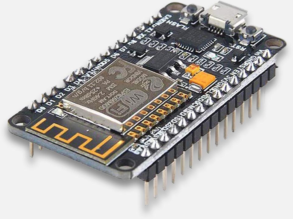
I started with this particular ESP8266 board: The MakerFocus ESP8266 (Amazon: USA and Germany).

Makerfocus – ESP8266
The beauty of an ESP8266 is not just that the used microcontroller is faster or cheaper. On top of that: it has more memory than most Arduino models (Flash memory of 4Mb, and typically more SRAM – however, EEPROM is more limited though).
The really cool part is the included Wi-Fi transceiver, allowing for a very easy way to get your Microcontroller connected to your WiFi and even the Internet. Even setting up a tiny web-server is super easy.
Just like an Arduino, it has a bunch of pins for interaction with additional components like switches, lights, relays, servo motors, sensors, etc.
These pin are often referred to as GPIO (General Purpose Input/Output pins), and the ESP8266 has at least 11 of these pins (depending on the model). This can be a few less than your good old Arduino, but newer ESP8266 models have more (Arduino Uno: 14, my Makerfocus ESP8266 has 16).
Compared to most Arduino’s, there could be one downside and that is that most ESP8266’s have only 1 or 2 analog pins (mine has only one it seems). The other pins are all digital.
So with these pins, we can do quite a lot of fun stuff, just like we can with an Arduino.
Note: There are quite a few manufacturers that use the ESP8266 chip for their little boards, and the ESP8266 comes in a few different versions as well. Keep in mind that the implementation and specifications can be different depending on the board manufacturer and the used chip (the original, v2 and v3 and there is the ESP32. The latter has even way more pins to play with).
Note: Some parts of the ESP8266 work with 3.3 Volts instead of 5 Volts (as seen with older Arduino models).
Note: to find a more detailed comparison, between Arduino and ESP8266, read this article at diyi0t.com.
In short: the ESP8266 houses a microcontroller (like your Arduino, just more powerful) and everything you need to get wirelessly connected, and that at a ridiculously low price of about $5 or even less.
Ad Blocking Detected Please consider disabling your ad blocker for our website.
We rely on these ads to be able to run our website.
You can of course support us in other ways (see Support Us on the left).
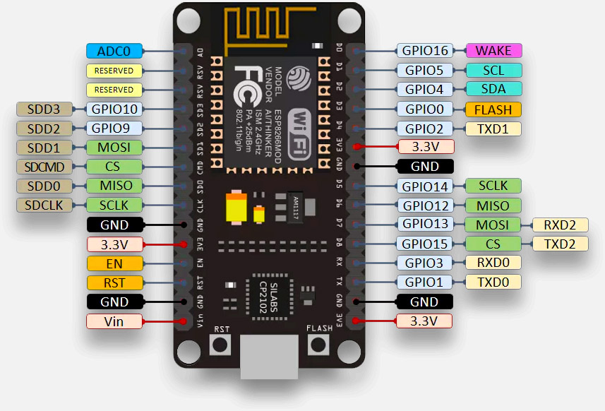
ESP8266 Pinout
For beginners the now following picture may not make much sense – and my Makerfocus ESP8266 has a very clear text on the back indicating what pin is what. Nevertheless, this picture may be good info for those not having an ESP8266 yet, or as reference for future projects.
Those that have looked at the pinout of an Arduino before; these pins will look very familiar.
Note: the ESP8266 can be powered by most simple adapters (5 – 12 Volt), from what I have read it will use 450 mA at peak moments, but power usage can drop even below 1 mA. So I think it is safe to say that your old adapter of one of your old cell phones will be more than adequate. 
Potential PIN Limitations?
While, on paper, the ESP8266 has plenty of GPIO pins, in reality, 6 of these are blocked off from use. GPIO6, GPIO7, GPIO8, GPIO9, GPIO10, and GPIO11 and are all unavailable to you. In addition, if you are using Serial input/output at all, attempting to use GPIO1 for leds may cause the device to reset.
(source)
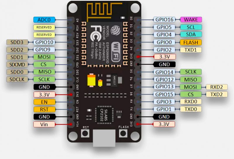
Makerfocus ESP8266 pinout
Using the ESP8266 as an Arduino
You may, like myself, already have some Arduino experience, and moving to an ESP8266 may look a little daunting at first especially when using it like a regular Arduino. Fear not, it is surprisingly easy to get started, below I’ll share my own experiences in hopes that it will be helpful for you as well.
Note: I’m focussing here on the ESP8266 that I own, a Makerfocus ESP8266, which set me back $10 for 2 modules. You can get them from Amazon in the USA and in Germany (both do deliver to a select number of other countries as well).
Preparing the Arduino IDE – Adding ESP8266 board support
So this is the first step where we have to begin, assuming of course you’d want to use the Arduino IDE for your ESP8266 module as well.
Obviously, the Arduino IDE is geared towards … ehm … Arduino’s. So the ESP8266 is by default not listed and we will need to add it.
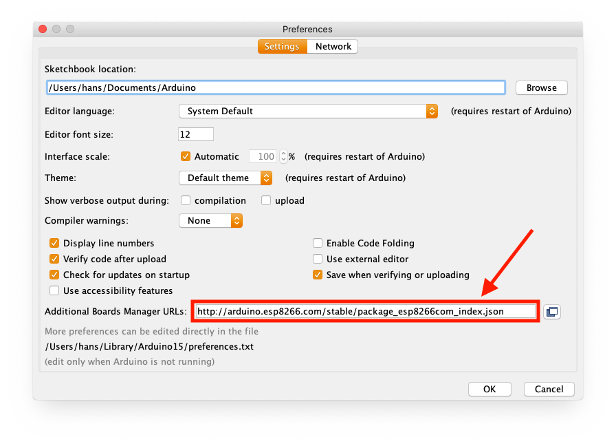
Start your Arduino IDE (always good to make sure you have the latest version) and go to “File” “Preferences” (on a Mac: “Arduino” “Preferences“).
In the lower part of the window that opened, you’ll find “Additional Boards Manager URLs:” where we have to paste this URL:
http://arduino.esp8266.com/stable/package_esp8266com_index.json
This URL will provide a ton of info for several EPS8266 models and boards.
ESP32 vs ESP8266
This article focuses on the ESP8266. It’s younger sibling, the ESP32, works in a similar fashion.
You’ll just need to use a different link. This one:
https://dl.espressif.com/dl/package_esp32_index.json
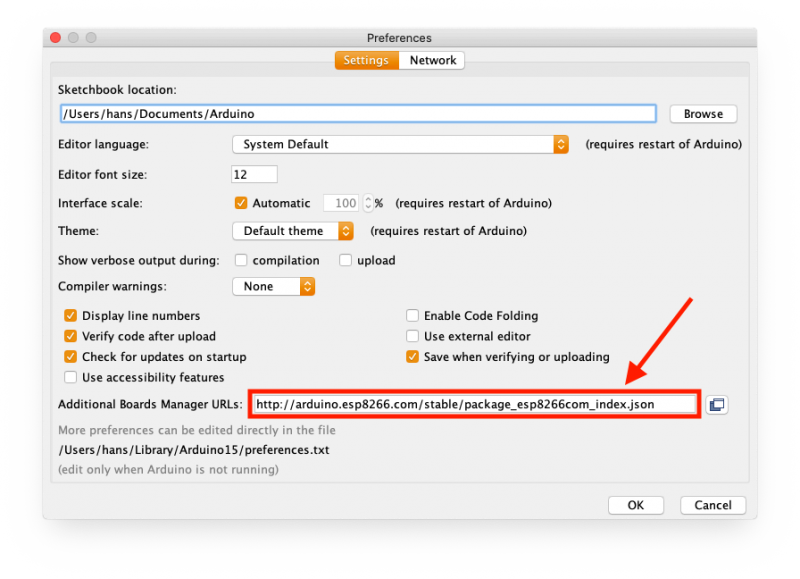
Arduino Preferences – Add your ESP8266
Activating the different ESP8266 boards
Now that we have told the Arduino IDE some of the details concerning ESP8266 based boards, time to “activate” them.
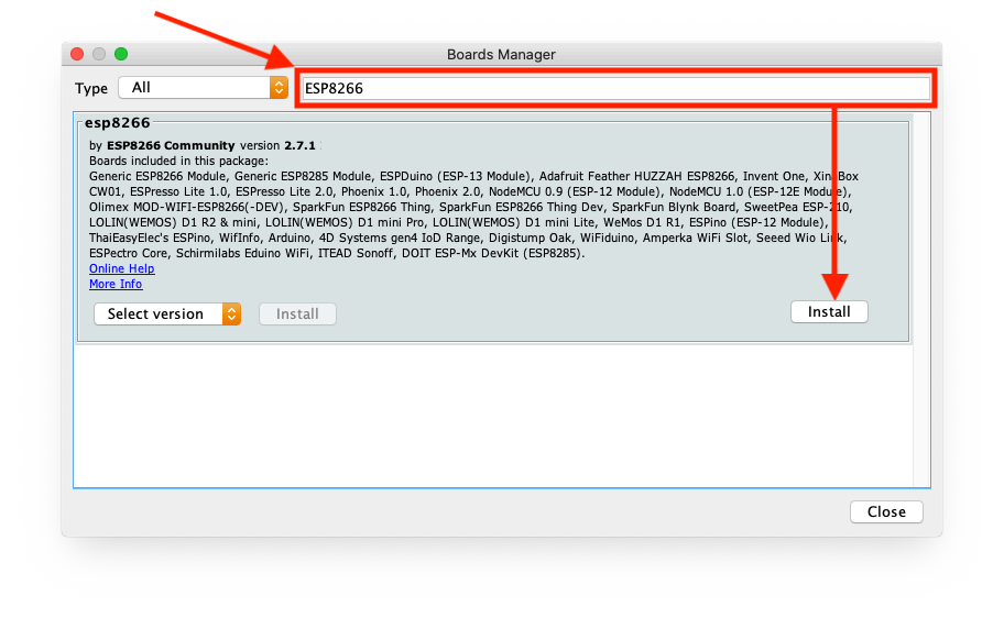
In your Arduino IDE go to “Tools” “Boards” “Board Manager” (you may have to look at the menu that shows something like “Board: XYZ” to find “Board Manager” as a sub menu item).
In the search box (next to “Type – All”), type “ESP8266” (without the double quotes). You should see something like the image below.
Click Install for the “esp8266” section.
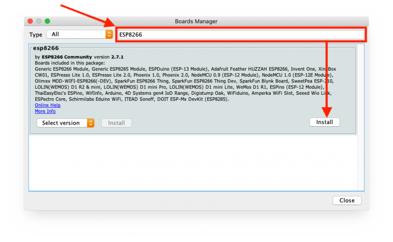
Arduino IDE – Add ESP8266 boards
Selecting the Right board for you
To be able to work with our ESP8266 board, we will need to select the right model under “Tools” “Boards“.
Short version …
For my “Makerfocus ESP8266” I selected the board “NodeMCU v1.0 (ESP-12E module)“.
Information below may be helpful in determining your board, in case it is not listed in the boards menu.
Now this can be quite confusing. Obviously with my luck, my Makerfocus ESP8266 was NOT listed as such, so I had to do a wild guess.
Not knowing what I’m doing, I just selected the “Generic ESP8266 module”, which worked. However after selecting this option, suddenly a ton of configurable details became visible, which made me think that there could be a more optimized board I could choose.
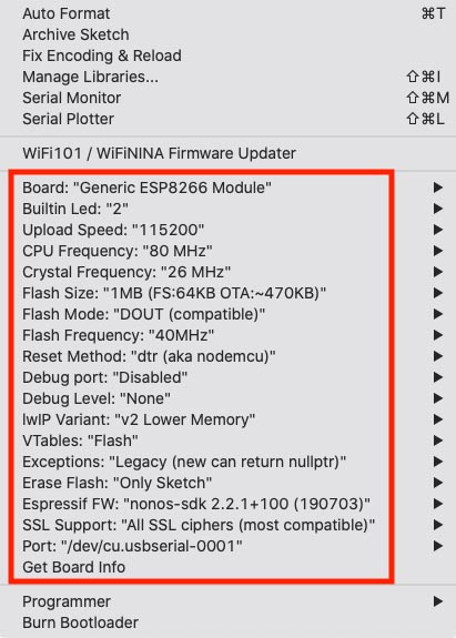
Generic ESP8266 – Wow, tons of options!
Obviously, as an ESP8266 beginner, I didn’t quite know what I was looking at. Of course, quite a few of these parameters I did understand, but I didn’t know how they correlated with my ESP8266 board.
So I went to my Amazon order to lookup what the heck I had purchased and found the following text “ESP8266 NodeMCU LUA CP2102 ESP-12E” which gave me a few hints. For one, I should probably give one of the NodeMCU boards a try. There were 2 listed: the v0.9 (ESP-12 module) and the v1.0 (ESP-12E module). So for me a dead give away that selecting the second option, the “NodeMCU v1.0 (ESP-12E module)” was my best option.
Ad Blocking Detected Please consider disabling your ad blocker for our website.
We rely on these ads to be able to run our website.
You can of course support us in other ways (see Support Us on the left).
Connecting your ESP8266 Module to your PC
So the next step is really easy of course, I just had to go find me a micro-USB cable.
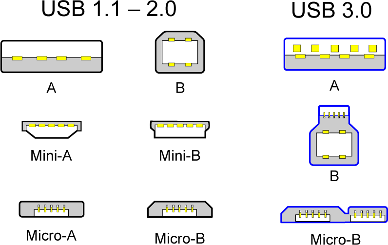
My Arduino Uno uses a USB-A to USB-B cable, but the connector on my ESP8266 was a USB micro-B connector. This is one of the most commonly used small USB connectors, as they are being used for cell phones, tablets, cameras etc.
All I had to do was go find a USB-A to USB micro-B cable.
Do not forget to select the correct serial port in the Arduino IDE (“Tools” “Port” – there can be additional text after the word “port”).
To give you an idea what the different USB connectors look like (source).
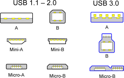
USB 2.x and 3.x connectors
ESP8266 Onboard LED
As seen with most Arduino models, most ESP8266 have 2 LEDs on board as well,… but initially I had no clue what “pin” they’d be connected to.
So after some searching I managed to get all the info I needed …
Inverted ON/OFF for onboard LEDs
Unlike the Arduino, both LEDs on my ESP8266 work opposite of what we would see on an Arduino (where HIGH = ON).
ON: When a pin is HIGH, then the LED is OFF.
OFF: If a pin if LOW then the LED is ON.
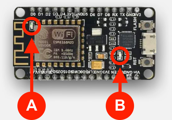
We have 2 LEDs on the Makerfocus ESP8266, and both are blue.
LED A (GPIO2) flashes when uploading our compiled sketch to the ESP8266.
ESP8266 LEDs
|
LED A |
LED B |
| Color |
Blue |
Blue |
| Pin |
2 |
16 |
| Name |
GPIO2 |
GPIO16 |
| In sketch Name |
D4
2 |
LED_BUILTIN
BUILTIN_LED
D0
16 |

ESP8266 – LEDs
To illustrate how this works, here what the “Blink” sketch would look like for your ESP8266 (no extra libraries needed):
1
2
3
4
5
6
7
8
9
10
| void setup() {
pinMode(LED_BUILTIN, OUTPUT); // Initialize LED_BUILTIN pin as output
}
void loop() {
digitalWrite(LED_BUILTIN, LOW); // LOW = Turn the LED on (opposite of Arduino)
delay(1000); // Wait for a second
digitalWrite(LED_BUILTIN, HIGH); // HIGH = Turn the LED off
delay(2000); // Wait for two seconds
} |
Ad Blocking Detected Please consider disabling your ad blocker for our website.
We rely on these ads to be able to run our website.
You can of course support us in other ways (see Support Us on the left).
Our first ESP8266 – LED on/off Webserver!
So this project shows how quick you can get started with an ESP8266 … ONLINE.
We are going to build a little webserver, which allows us to toggle a LED ON and OFF via the web browser on our computer.
In this project we will not use any additional hardware, so we only need our ESP8266 board.
For power this can either be connected to your computer’s USB port to a USB adapter/charger.
Libraries used:
- ESP8266Wifi and WiFiClient – To handle all WiFi needs
- ESP8266WebServer – Basically our web server

You will find that these most likely are already installed.
Controlling the LEDs
This shouldn’t be too hard, if you’ve played with an Arduino before.
We need to determine which of the 2 LEDs we’d like to use, and we need to make sure the appropriate LED pin is set to output.
For this purpose, and because the LOW and HIGH are the opposite of what we’d expect on an Arduino, I’ve defined a few constants (not really a constant, rather a compiler directive).
One for the LED pin, and two for the LEDon and LEDoff state.
I selected LED B (in figure above), which is GPIO16 or in other words: pin 16.
1
2
3
4
5
6
7
8
9
10
11
| /* LED details */
#define LEDon LOW
#define LEDoff HIGH
#define LEDPin 16
...
void setup() {
// Enable internal LED
pinMode(LEDPin, OUTPUT);
...
digitalWrite(LEDPin, LEDon);
... |
Since switching a LED on or off should trigger a message in the serial monitor, and it should load a new page (different button state), I glued some of these steps into a function:
1
2
3
4
5
6
| void SetLED(byte LedPinNo, byte LedState) {
digitalWrite(LedPinNo, LedState);
Serial.print("LED turned ");
Serial.println(LedState==LEDon ? "ON" : "OFF");
handleButtonDisplay();
} |
Just in case you are wondering:
The function “handleButtonDisplay()” is something I’ll discus in the HTML part – its task is to push out the correct HTML for the buttons, depending on the LED state (on or off).
Setting up a WiFi connection
Most of the WiFi work is handled by the included libraries (ESP8266WiFi and WiFiClient). A few manual things are required though.
When the ESP8266 powers up, we’d like to to connect to our home WiFi, so we need to define the SSID (the “name” of you WiFi).
If you’ve setup your home WiFi halfway correctly, then we will also need to provide a password.
We define them as such (replace the info with the correct info for your WiFi!):
1
2
3
| /* WiFi details */
#define ssid "MyWifiSSID"
#define password "MyPassword" |
The WiFi then gets initialized in a super simple way:
First we start WiFi, and then we ruin through a loop until we connect (note: this is not the best method in case you had the wrong password or a typo in the SSID of your WiFi);
1
2
3
4
5
6
7
8
9
10
11
12
13
14
| void setup() {
...
WiFi.begin(ssid, password);
while (WiFi.status() != WL_CONNECTED) {
delay(500);
Serial.print(".");
}
...
// Connected! Show IP address
Serial.println("");
Serial.println("WiFi connected");
Serial.print("IP address: ");
Serial.println(WiFi.localIP()); |
Can it be any easier? Aren’t libraries just great! 
Serial Monitor Output
Since this is all new to us, we’d like to see some output from the ESP8266 through the serial monitor build into the Arduino IDE.
Initially, the serial monitor will show some garbage characters. This is actually not garbage, but debug info send from the ESP8266 at a baudrate of 74880. This weird baudrate is said to be a non-standard baudrate so we know information is debug info (versus application specific info). Source: ESP8266.com.
This is done exactly the same as with an Arduino, but we just pick a higher speed than usual … since we can
So in the setup() we will need to initialize the debug monitor, so we can use Serial.print and Serial.println to send information to the serial monitor. (If you’re new to this: more details can be found here)
1
2
3
4
5
6
7
| void setup() {
...
// Enable serial monitor
Serial.begin(115200);
...
Serial.println("Configuring access point...");
... |
The basic idea is to show 2 buttons, one for ON and one for OFF.
Naturally, it would be nice if these buttons are the same size (we’ll handle that with some CSS), and they should reflect the state of the LED.
So when the LED is ON, the “ON” button should be disabled, and the OFF button enabled, and vice versa.
This can be done with the disabled parameter of the buttons we are about to use.
When clicking on the buttons we should have the browser load a new page, for this we have 2 “pages” on our ESP8266 webserver to switch a LED on (LEDOn) and off (LEDOff). So:
http://<ip address of ESP8266>/LEDOn
and
http://<ip address of ESP8266>/LEDOff
To handle the buttons, we technically we could work with a HTML <FORM>, but with JavaScript there is no need for this since we can use location.href to set the location that needs to be opened.
So all this combined in “actual” HTML:
1
2
3
4
5
6
7
8
9
10
| <style>
input[type="button"] {
width: 64px;
padding: 2px;
margin-bottom: 4px;
}
</style>
<input type="button" onClick="location.href='/LEDOn';" value="ON">
<input type="button" onClick="location.href='/LEDOff';" value="OFF" disabled> |
This should result in something like this in your browser:

Buttons
To generate the correct HTML, I’ve created a function for this, called “handleButtonDisplay()“.
It’s main purpose is to combine the HTML code and tag the correct button as disabled, depending on the LED state.
1
2
3
4
5
6
7
8
9
10
11
12
13
14
15
16
17
18
19
| void handleButtonDisplay() {
bool LEDIsOn = (digitalRead(LEDPin)==LEDon);
String HTML = "";
HTML += "<style>input[type=\"button\"] { width: 64px; padding: 2px; margin-bottom: 4px; }</style>";
HTML += "<input type=\"button\" onClick=\"location.href='/LEDOn';\"";
HTML += (LEDIsOn ? "Disabled" : "" );
HTML += " value=\"ON\">";
HTML += "<br>";
HTML += "<input type=\"button\" onClick=\"location.href='/LEDOff';\"";
HTML += (!LEDIsOn ? "Disabled" : "" );
HTML += " value=\"OFF\">";
server.send(200, "text/html", HTML);
} |
Setting up the ESP8266 Web Server
With the ESP8266WebServer library, things get really easy as well.
First we need to define a global variable to hold our ESP8266WebServer object (don’t overthink it!), which we will call “server” and which listens to port 80 (the default port).
1
2
3
4
5
6
| #include <ESP8266WebServer.h>
...
ESP8266WebServer server(80);
...
void setup() {
... |
Before we can start the server, we will first need to have a network connection, so in out code we will first make sure the WiFi connection is up and running. After that we can start the web server with:
1
2
| // Start webserver
server.begin(); |
Easy right?
Handling the call for “pages” (eg. LED on/off) on the ESP8266 Web Server
The ESP8266WebServer is put together really well, and we can define “events” and we need to do this before we start the web server.
In this example we will keep it simple of course, but we want to define 3 events:
- The “start” page is being opened (http://<ip address>)
- When we want to switch the LED ON (http://<ip address>/LEDOn)
- For switching the LED OFF (http://<ip address>/LEDOff)
I won’t go too much into detail, but in essence we can give the ESP8266WebServer object event conditions when a certain page (link) is being asked for. I intentionally wrote this in a consistent way, but it can be written shorter.
To assign the events:
1
2
3
4
| // Define event handlers
server.on( "/", []() { handleButtonDisplay(); });
server.on( "/LEDOn", []() { SetLED(LEDPin, LEDon); });
server.on( "/LEDOff", []() { SetLED(LEDPin, LEDoff); }); |
Here we can read:
When “/” is being called, call the function handleButtonDisplay().
If however “/LEDOn” is being called, call the function SetLED(LEDPin, LEDon).
And finally, when “/LEDOff” is being called, call the function SetLED(LEDPin, LEDoff).
And that’s basically it … the web server can now be started as illustrated before.
ESP8266 Web Server Sketch
In the code below I have combined all the steps I’ve just discussed.
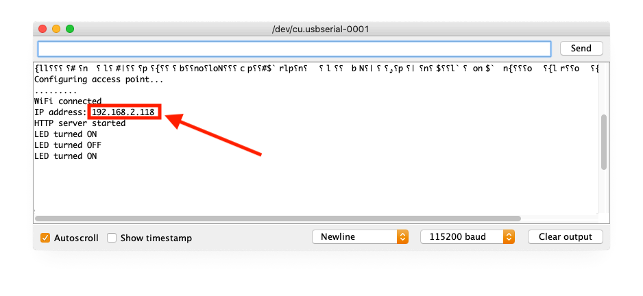
Once this code runs, you will see a few messages in the serial monitor, and one of those messages will display the IP address of your ESP8266.
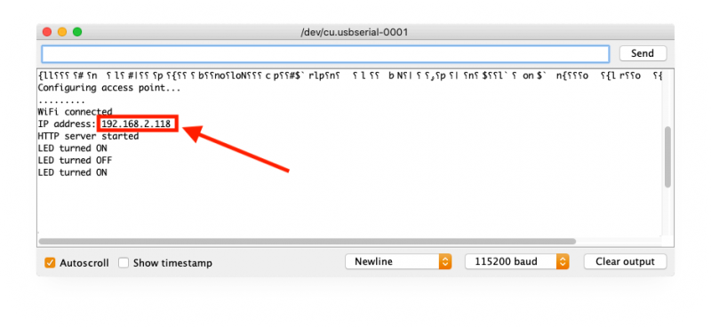
Serial Monitor tells us our IP address
Now that we know the IP address, go to your PC, open a browser and type the IP address and press Enter.
The buttons should appear and you can actually click them to turn the LED on or off.
1
2
3
4
5
6
7
8
9
10
11
12
13
14
15
16
17
18
19
20
21
22
23
24
25
26
27
28
29
30
31
32
33
34
35
36
37
38
39
40
41
42
43
44
45
46
47
48
49
50
51
52
53
54
55
56
57
58
59
60
61
62
63
64
65
66
67
68
69
70
71
72
73
74
75
76
77
78
79
80
81
82
83
84
85
86
87
88
89
90
91
92
93
94
95
96
97
98
| #include <ESP8266WiFi.h>
#include <WiFiClient.h>
#include <ESP8266WebServer.h>
/* LED details */
#define LEDon LOW
#define LEDoff HIGH
#define LEDPin 16
/* WiFi details */
#define ssid "MyWifiSSID"
#define password "MyPasswors"
ESP8266WebServer server(80);
void setup() {
// Enable internal LED
pinMode(LEDPin, OUTPUT);
// Enable serial monitor
Serial.begin(115200);
// Start WiFi
Serial.println();
Serial.println("Configuring access point...");
WiFi.begin(ssid, password);
// Wait for the WiFi connection
while (WiFi.status() != WL_CONNECTED) {
delay(500);
Serial.print(".");
}
// We are connected! Show IP address
Serial.println("");
Serial.println("WiFi connected!");
Serial.print("IP address: ");
Serial.println(WiFi.localIP());
// Define web server event handlers
server.on( "/", []() { handleButtonDisplay(); });
server.on( "/LEDOn", []() { SetLED(LEDPin, LEDon); });
server.on( "/LEDOff", []() { SetLED(LEDPin, LEDoff); });
// Start webserver
server.begin();
Serial.println ( "HTTP server started" );
// Do some blinking so we know we're up and running
SetLED(LEDPin, LEDon);
delay(100);
SetLED(LEDPin, LEDoff);
delay(100);
SetLED(LEDPin, LEDon);
delay(100);
SetLED(LEDPin, LEDoff);
delay(100);
}
void loop() {
// Keep repeating: looking for web server events
server.handleClient();
}
void SetLED(byte LedPinNo, byte LedState) {
// Set LED on or OFF, output serial monitor info, and send the updated HTML
digitalWrite(LedPinNo, LedState);
Serial.print("LED turned ");
Serial.println(LedState==LEDon ? "ON" : "OFF");
handleButtonDisplay();
}
void handleButtonDisplay() {
// Read the current LED state
bool LEDIsOn = (digitalRead(LEDPin)==LEDon);
// Build a String with all the HTML in it.
String HTML = "";
HTML += "<style>input[type=\"button\"] { width: 64px; padding: 2px; margin-bottom: 4px; }</style>";
HTML += "<input type=\"button\" onClick=\"location.href='/LEDOn';\"";
HTML += (LEDIsOn ? "Disabled" : "" );
HTML += " value=\"ON\">";
HTML += "<br>";
HTML += "<input type=\"button\" onClick=\"location.href='/LEDOff';\"";
HTML += (!LEDIsOn ? "Disabled" : "" );
HTML += " value=\"OFF\">";
// Send the string to the browser as HTML text
server.send(200, "text/html", HTML);
} |
Comments
There are 6 comments. You can read them below.
You can post your own comments by using the form below, or reply to existing comments by using the "Reply" button.
Hi Hans !!
Impeccable work. I have seen the ESP8266 board, and it will surely be one of the next purchases. Having the built-in Wi-Fi on the same board as the microcontroller is a great advantage and at almost the same price !!!
Thank you very much for all your contributions !!
Greetings from Argentina!!
German
escalatordude
Thanks German!
It’s even better: way more memory, smaller, faster, … I haven’t tried the ESP32 yet (twice as expensive, still much cheaper than an original Arduino Uno), which is supposed to be even better (dual core!).
Thanks again for the compliments!
Hans
Hi Hans,
I am really impressed what you’ve done with the ESP8266. I tried it and it worked immediately. Now I’m trying to use the webserver to control the color of my RGBW-LED strip. But I have no idea how to get the values from the range – object to my arduino.
The html -code for the range object is
I can see the value from the range-object in the output-object with the name “w”. How do I get this value to my script?
With an earlier project I changed the colors using 4 analog input and mapped them to my variables
And with the webserver I want to control my strip-color using the range-objects from html5.
kind regards :) Georg
Georg
Hi Georg!
Thank you for the compliments, and nice to see it work right away.
Looking at what you are trying to do, one could use GET or POST values, so it returns something like this (I usually start with super simple formatting to keep experimenting easy):
So when clicking Submit, you’ll get a URL something like this:
No you need to parse the parameters, and the ESP8266WebServer library has some functions for that, like for example server.arg() and would return the red value passed from the HTML form. Some functions are shown here and I found this example on StackExchange.
If you’d rather use POST (instead of GET), then an example that shows this concept can be found here.
Hope this helps
Hans
Hi Hans,
now I am finished programming my websever to receive the color/speed/programmnumber and it works really fine. When I’m registered in your forum I will post the code. But now I have several problems to run the RGB-Strip code on the 8266 because it is always resetting the chip because of the watchdog (it seems so).
Georg
Awesome!
Too bad you’re running into an issue – I’m working on a project to do all my led effects with an ESP8266 as well, never experienced any issues though?
Maybe some of my code is helpful. This is what I put in the beginning of my code – look at the comments as they may be useful.
The comments are based on info I found online.
Hans