Reading Ambient Light with an LDR
First thing we should know, is that an LDR (Light Dependent Resistor, or Photo resistor) is basically a resistor that change resistance depending on light. More light means less resistance. Less light means more resistance.
LDR’s have been around for a very long time (as a kid I already played with LDR’s) and cheap. Not to mention: pretty rugged and very cheap.
Now when connecting an LDR to you Arduino, one would automatically go for one of the Analog pins, but analog pins are slow when it comes to reading them. Therefor in this article, we will also show you how to connect them to be used with a Digital pin, which gives us an ON/OFF state instead of a value.
Measuring light and LDR
Note that the phrase “measuring light” is not really what I would call this.
LDR’s are not a all that accurate way of measuring light as such.
It is however a great tool for detecting ambient light … roughly.
LDR on an Arduino Analog Pin
This would be the most used and most obvious way to use an LDR, as it fluctuates resistance, producing many values.
In this setup we will make it that the value read from the Analog pin will actually increase as light increases. For this we use a tiny circuit that pushes power through the LDR. Since the LDR decreases its resistance as light increases, more “power” will pass through it to the Analog pin, which results in the Arduino “reading” a higher value.
The analog pin will read values between 0 and 1023, so it converts the analog signal to a digital representation – also called Analog Digital Converter (AD or ADC), which is build into the Arduino.
All we need is:
- Arduino (I used an Uno, clones as of late have been reported to be problematic at times)
- USB cable to connect the Arduino to our computer
- Arduino IDE (free download)
- an LDR (duh!)
- a 100KΩ resistor (brown-black-yellow, or see our Resistor Calculator)
- 3 wires
- a small breadboard
The setup is very simple:
In words:
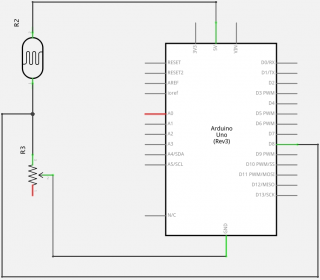
Connect +5V of the Arduino to one pin of the LDR (LDR pins can be swapped, so no worries about polarity here).
Connect the other pin of the LDR to A0 (analog pin of the Arduino) and one pin of the 100KΩ resistor.
Connect the other pin of the 100KΩ resistor to GND of the Arduino.
Schematic (done with Fritzing):
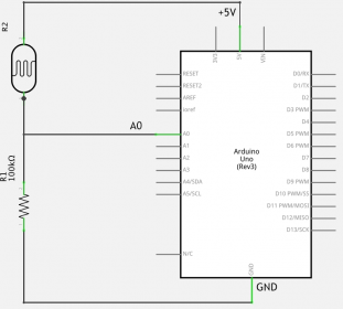
Arduino – LDR connected to an Analog Pin
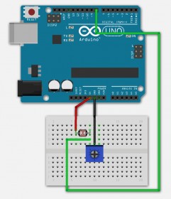
Breadboard drawing (done with Fritzing):
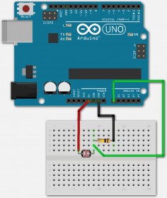
Arduino – LDR connected to an Analog Pin
The sketch is straight forward as well, and will display the read analog value through the serial port so we can see what is happening.
1
2
3
4
5
6
7
8
9
10
11
12
13
| #define LDRpin A0 // pin where we connected the LDR and the resistor
int LDRValue = 0; // result of reading the analog pin
void setup() {
Serial.begin(9600); // sets serial port for communication
}
void loop() {
LDRValue = analogRead(LDRpin); // read the value from the LDR
Serial.println(LDRValue); // print the value to the serial port
delay(100); // wait a little
} |
Connect your Arduino with the USB cable to your computer.
Start the Arduino IDE and make sure you select the right board and serial port.
For selecting the right board, go to “Tools” “Board” “Arduino Uno” (if you’re using an Arduino Uno), and for the right port, go to “Tools” “Port” “/dev/cu.usbmodem1411 (Arduino Uno)” (this is on my Mac, your Mac or PC might show something different).
Copy and past the sketch above into the Arduino IDE (either paste over the existing empty code, or open a new sketch – “File” “New“) and click the “Upload” button, which in the figure below is button “B“.
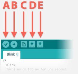
Arduino Software – Useful shortcuts
Next start the “Tools” “Serial Monitor” so we can see the output, which will be something like this:
...


949

945

943

917

838

837

832

796

748

709

706

704

692

689

698


...
Without doing anything, the value seems to hover around 917 … 950, moving my hand over the sensor however (limiting light) will make it drop below 800.
Note that these values will probably be different in your environment.
Play a little with it and see what the values do.
LDR on an Arduino Digital Pin
Now that we have seen the LDR work on an Analog pin, time to look at what will happen with a digital pin on your Arduino.
Keep in mind that the digital pin only returns a 1 or a 0 (zero), unlike the Analog pin, which is useful if something needs to be switched ON or OFF, like for example lights.
It seems that for an Arduino, a voltage threshold of 2.2 V triggers either 1 or 0. Also note that reading this value goes much faster than reading an Analog pin, which is crucial for applications where speed is of the essence (for example the Boblight application).
So lets test this.
For this purpose I will use a potentiometer, which is a variable resistor so I can fine tune when it’s light enough to go ON (1) and dark enough to go OFF (0). The main reason for this is that your ambient light (environment) will be different from mine. Not to mention: where ever you are going to apply this, might be in a darker or lighter place then where you’re building your Arduino setup.
We will use the same components as before, however we will replace the resistor with a potentiometer.
A potentiometer typically has 3 pins. The one in the middle is the variable dial and the ones on the left and right are basically a resistor. The variable dial slides over this resistor and “taps” off a resistance between zero and the max resistance of the resistor.
Maybe this drawing explains it better:
R is the “full” resistor. It has two pins: R1 and R2.
If you’d use a multimeter and measure the resistance between pins R1 and R2 then you’ve read the resistance of the resistor R.
The wiper (V) creates a “shortcut”, so if you’d measure the resistance between R1 and V, you’d only measure the resistance of R that is found between the pins R1 and V. Or if you’d measure the resistance between R2 and V, you’d be measuring the resistance of R between R2 and V.
So moving the wiper, would change the distance between, for example, R1 and V – the longer the distance between these two pins, the higher the resistance between the pins R1 and V. Makes sense?
In our setup we use only 2 of the 3 pins, the middle one and one on the right or left.
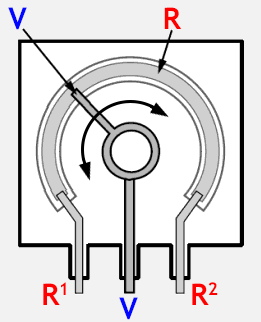
How a potentiometer works
All we need is:
- Arduino (I used an Uno, clones as of late have been reported to be problematic at times)
- USB cable to connect the Arduino to our computer
- Arduino IDE (free download)
- an LDR (duh!)
- a 10KΩ potentioneter (feel free to try higher or lower values)
- 3 wires
- a small breadboard
In words:
Connect +5V to one pin of the LDR (LDR pins can be swapped, so no worries about polarity here).
Connect the other pin of the LDR to Digital pin 8 (of the Arduino) and the outside pin of the 10KΩ potentiometer (either left or right).
Connect the middle pin of the 10KΩ potentiometer to GND of the Arduino.
The following drawings might look a lot different, but they really are not that different than the analog example.
We replace the 100KΩ resistor with a 10KΩ potentiometer, and instead of the Analog Pin A0, we use the Digital Pin 8.
Schematic (done with Fritzing):
Arduino – LDR connected to an Digital Pin
Breadboard drawing (done with Fritzing):
Arduino – LDR connected to a Digital Pin
The sketch is going to be almost the same as the one for the Analog method.
We only changed the fact that we read a digital signal from pin 8.
1
2
3
4
5
6
7
8
9
10
11
12
13
| #define LDRpin 8 // pin where we connect LDR and resistor
int LDRValue = 0; // result of reading the analog pin
void setup() {
Serial.begin(9600); // sets serial port for communication
}
void loop() {
LDRValue = digitalRead(LDRpin);// read the value from the LDR
Serial.println(LDRValue); // print the value to the serial port
delay(100); // wait a little
} |
Connect your Arduino with the USB cable to your computer.
Start the Arduino IDE and make sure you select the right board and serial port.
For selecting the right board, go to “Tools” “Board” “Arduino Uno” (if you’re using an Arduino Uno),
And for the right port, go to “Tools” “Port” “/dev/cu.usbmodem1411 (Arduino Uno)” (this is on my Mac, your Mac or PC might show something different).
Copy and past the sketch above into the Arduino IDE (either paste over the existing empty code, or open a new sketch – “File” “New“) and click the “Upload” button.
Next start the “Tools” “Serial Monitor” so we can see the output, which will be something like this:
1
2
3
4
5
6
7
8
9
10
11
12
13
14
| 1
1
1
1
1
1
1
1
1
1
1
1
1
1 |
This could also be a load of zero’s.
Now gently turn the knob of the potentiometer until it switches values. So if you started with a lot of 1’s, turn slowly until they become zero’s or the other way around. Do not turn that knob too fast, you’ll have to look for the sweet spot where it switches output value.
Once you have found the sweet spot, hold you hand over the LDR and you’ll see it change. If not: tune that potentiometer a little more until it does.
LDR on an Arduino Digital Pin Expanded
Now, with one LDR on a digital pin, we can only read an ON and OFF state, which might not be all that great if you want more than 2 intervals (range OFF and range ON).
Say we’d like to 3 light levels, then 2 LDR’s on each their own digital pins might do the trick – all under the assumption that reading analog pins is too slow of course. Below an example how this can be done. You can expand this idea with as many LDR’s as you like and your Arduino can handle.
Basically what we do is make one LDR switch to ON quicker than the other LDR. For that purpose they both have their own potentiometer so we can tune them as we see fit for each “level”.
For the second LDR we use pin 7 (in the Sketch) – feel free to use another pin, but make sure to adjust the sketch accordingly.
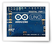
Schematic (done with Fritzing):
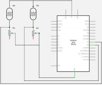
Arduino – Double LDR connected to an Digital Pin
Breadboard drawing (done with Fritzing):
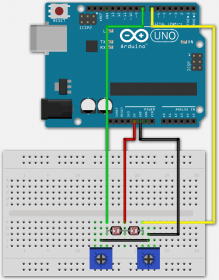
Arduino – Double LDR connected to an Digital Pin
The sketch fort this setup:
1
2
3
4
5
6
7
8
9
10
11
12
13
14
15
16
17
18
19
20
| #define LDRpin1 7 // pin where we connect LDR and resistor
#define LDRpin2 8 // pin where we connect LDR and resistor
int LDRValue1 = 0; // result of reading the digital pin
int LDRValue2 = 0; // result of reading the digital pin
void setup() {
Serial.begin(9600); // sets serial port for communication
}
void loop() {
LDRValue1 = digitalRead(LDRpin1);// read the value from the LDR
LDRValue2 = digitalRead(LDRpin2);// read the value from the LDR
Serial.print(LDRValue1); // print the LDR1 value to the serial port
Serial.print(" "); // print a space
Serial.println(LDRValue2); // print the LDR2 value to the serial port
delay(100); // wait a little
} |
Depending on the potentiometer settings and your ambient light you will see sets of “0 0”, “1 0”, “0 1” or “1 1” flying by.
First turn both potentionmeters to one far end.
Setting the “low” level:
Turn down your ambient light until the point that you consider “dark”.
Turn both potentiometers until you only see sets of “0 0”. This will be our “dark” level.
Setting the “medium” level:
Set your ambient light to what you’d consider “medium”.
Very slowly turn up only one of the potentiometers, let’s say LDR1, until sets “1 0” start appearing.
(if you’d do this with LDR2 instead, sets of “0 1” should appear)
Setting the “high” level:
Now crank up the ambient light to what you’d consider “high” (anything brighter will be consider “high” as well).
Very slowly move up the potentiometer of LDR2 until sets of “1 1” start appearing.
Play a little with this and you’ll get the hang of the fine tuning part.
The following example code gives you an idea what you could do with this:
1
2
3
4
5
6
7
8
9
10
11
12
13
14
15
16
17
18
19
20
21
22
23
24
25
26
27
28
29
| #define LDRpin1 7 // pin where we connect LDR and resistor
#define LDRpin2 8 // pin where we connect LDR and resistor
int LDRValue1 = 0; // result of reading the digital pin
int LDRValue2 = 0; // result of reading the digital pin
void setup() {
Serial.begin(9600); // sets serial port for communication
}
void loop() {
LDRValue1 = digitalRead(LDRpin1);// read the value from the LDR
LDRValue2 = digitalRead(LDRpin2);// read the value from the LDR
Serial.print(LDRValue1); // print the LDR1 value to the serial port
Serial.print(" "); // print a space
Serial.print(LDRValue2); // print the LDR2 value to the serial port
if((LDRValue1==1)&&(LDRValue2==1)) {
Serial.print(" -> HIGH"); }
else if ((LDRValue1==1)&&(LDRValue2==0)) {
Serial.print(" -> MEDIUM"); }
else if ((LDRValue1==0)&&(LDRValue2==0)) {
Serial.print(" -> LOW"); }
Serial.println(" lighting");
delay(100); // wait a little
} |
Output example (in a darker room, while slowly moving a flashlight towards both LDRs) could look like this after tuning the potentiometers:
1
2
3
4
5
6
7
8
9
10
11
12
| 0 0 -> LOW lighting
0 0 -> LOW lighting
0 0 -> LOW lighting
0 0 -> LOW lighting
0 0 -> LOW lighting
1 0 -> MEDIUM lighting
1 0 -> MEDIUM lighting
1 0 -> MEDIUM lighting
1 0 -> MEDIUM lighting
1 1 -> HIGH lighting
1 1 -> HIGH lighting
1 1 -> HIGH lighting |
To apply this in, for example, the Boblight project (untested), you could try something like the code below.
It’s just an example and to make comparing easier, I’ve added both LDRValue where I multiplied the second LDRvalue with 10.
So we get theoretically could get results like 0, 1, 10 and 11. As mentioned before, due to the overlap one value (10) will not occur, so we have { 0, 1, 11 } as possible outcomes.
1
2
3
4
5
6
7
8
9
10
11
12
13
14
15
16
17
18
19
20
21
22
23
24
25
26
27
28
29
| #define LDRpin1 7 // pin where we connect LDR and resistor
#define LDRpin2 8 // pin where we connect LDR and resistor
... // some other code of your project
void loop() {
... // your project loop
AdjustBrightness();
... // More optional project code
}
void AdjustBrightness() {
int LDRValue = 0; // result of reading the digital pin
LDRValue = digitalRead(LDRpin1);// read the value from the LDR
LDRValue = LDRValue + (digitalRead(LDRpin2)*10);// Add the value from the next LDR
if(LDRValue==0) {
// Dark, so set LED brightness for example to 50%
}
else if(LDRValue==10 {
// Medium, so set LED brightness for example to 70%
}
else if(LDRValue==11) {
// Bright light, set LED brightness for example to 100%
}
} |
Conclusion
With an LDR we can read ambient light, even though it’s not 100% accurate and suitable for measuring. It’s more of a detection tool for ambient light.
We can use an Analog pin or a Digital pin, each with it’s own purpose and application.
The use of the Analog pin gives you a range of 0 … 1023 for the measured results.
Measuring like this gives you a range to work with, but is relatively slow and in certain situations (Boblight for example), this will not be fast enough for practical use.
The Digital Pin approach is much faster and could be expanded by adding another LDR on a second pin and fine tune the potentiometer of that second LDR to a different sensitivity, so that in essence you could have 3 “values” or light levels … (there will be an overlap, so the 4th value would not occur)


Comments
There are 28 comments. You can read them below.
You can post your own comments by using the form below, or reply to existing comments by using the "Reply" button.
this is my working code for one LDR with digital output.
izeman
Cool – does it work as you’d hoped it would work?
hans
it works EXACTLY i was expecting it to work. well – with only TWO states of course. so no continous adjustment of brightness, but it’s a beginning. :)
izeman
Awesome!!!

hans
how to use LDR without delay .. if LDR can light dark light .. .. when LDR is not light. bright lights
Amirul syafiq
Hi Amirul,
I’m not quite sure what you’re asking?
You mean how to use the LDR without Arduino? Or to control a light through the Arduino, depending on ambient light brightness?
hans
Idea Is Good..The Main Feature is Using Arduino Board Can Control Light Sensor Sensitivity ,, But As Use Simple Project This Idea Also Good>> https://www.youtube.com/watch?v=laY6CtZShX8
kabir
Thanks Kabir,
that indeed looks good too – probably a more rugged approach and therefor maybe more suitable for certain projects. Thanks for sharing!
hans
hello guys, i want use LDR on digital pin as i want only complete ON/OFF ambilight. I have pi2+hyperion+WS2812b freshly build setup. I want it to be OFF while some amout of light “daylight” as i find it usefull in very bright light. and when dusk come turn ambilight ON ( i have set permanent 70% brightness). Can you please be so kind and help me with this?it shouldnt be difficult to do for you :)
one more question- if im wathcing TV in bright light and ambilight is OFF dark come will it automatically turn ON or i need reboot my kodi for it to turn on?
thanks a lot!
Michal
i will point you in the right direction. i guess finding the solution is quite obvious then :)
a hint: take a closer look on the second half of the code:
izeman
Hi Michal!
(and thanks IzeMan!!!)
A related forum topic should get you started:
Add ambient light detection
It’s the reverse of what you want, but it will get you started,…
hans
thanks guys!
I did this. can it possibly work as i want it to?
Is best way to turn off ambilight just set brightness to 0% ?
will it need reboot arduino to refresh state? in that case ist not very efficient.
Michal
Hi Michal,
that looks about right (can’t test it at this time), and if you call “AdjustBrightness()” in the “loop()”, it should automatically adjust, no reboot needed. Unless this functions slows down your Arduino too much and you only call it once in “setup()” – in that case a restart of the Arduino might be needed.
hans
and if I want to make a counter with 2 ldr, Example when the sensor1 is active, that means the person is in front of the door. Sensor1 active but the sensor2 is till inactive, when the person is through the door the sensor2 become active as sensor1. When the person moves forward the sensor1 become inactive but the sensor 2 is still active until the person moves from the door then sensor2 become inactive that means the person entre, otherwise if sensor1was active and then inactive before the sensor2 become active or the sensor2 become inactive in the same time as sensor1 that means the operation was cancelled.My email
leo
Hi Leo,
sounds like you like to “hand-over” the detection.
So start with LDR1 active, if LDR2 becomes active as well, then LDR2 is the only active one. Something like that?
I’d start by detection both sensors at the same time, and program your logic based on the results of either sensor.
Something like:
Obviously, the values tested is something you should try and find out which values work.
However, for detecting a person (day or night), a PIR might work better, which would work with Arduino as well and eliminates the light sensitivity, and detects motion instead.
hans
[…] http://www.tweaking4all.com/hardware/arduino/arduino-light-sensitive-resistor/ […]
Hi! I would like to know if there is a way to control multiple LDRs with one potenciometer. I have 5 diferent LDR (They measure the light of some spaces in a room) and need them to have the exact same sensibility.
Thanks for the help
Beatriz
Hi Beatriz!
LDR’s are notoriously known for not being very accurate.
So the best approach would be replacing the resistor with a 100K potentiometer (as you already mentioned), and test the results for each LDR through the serial monitor.
You may not get the exact same results for each setup and LDR, so you may have to work with ranges when calculating actions on your Arduino.
I’m just not quite sure what your setup looks like? 5 Arduino’s with LDR and potentiometer? Or one Arduino with 5 LDRs?
hans
Hi Hans, thanks for the attention
I have one arduino with five LDRs and one potentiometer. Each one of these LDRs activate one part of a Processing code when covered by a shadow (they display diferent animations, this is the basic idea of how it should work when finished: https://drive.google.com/file/d/1Jcx-5UXa9JpEh5UcLKBQNepOPdfFuDRe/view?usp=sharing). Using the info on the “LDR on an Arduino Digital Pin” i managed to make it work with one LDR, but i am having difficult to adapt for multiple LDRs. It’s my first time using arduino and i am kinda lost =/
Beatriz
Hi Beatritz,
When using multiple LDR’s, you’d basically rebuild the electronics the same way you did for the first LDR, like shown in figure 7.
The code would repeat as well, as you can see in the code below figure 7.
I’m guessing that “calibrating” the LDRs so they behave the same, is the main challenge and for that you’d need a setup where you can shed light consistently on the LDRs. I’d take a few different steps; no light, max light, and a few steps in between. For each step you’ll need to turn the potentiometer of each LDR until the serial output gives approximately the same output for all LDRs. I’m pretty sure you will not get it 100% to match, but probably close enough to determine the LDRs are “the same” when the rerun value is in a defined range.
In the examples I’ve used a digital pin, to get a clear on and off state, but you could also use an analog pin and see actual values, so you can define multiple states.
hans
hello, i want to ask what component should i get to design project monitoring bulb intensity connect to web based system.
khairul
Hi Khairul,
An LDR could do that, but it all depends how accurate and sensitive you want it to be.
If you’d like to do this in LUX, then see this project for a suggested calculation.
I’m a little skeptical how accurate this is, but I could be wrong.
As for linking this to a web based system, you could setup your Arduino to push data to the server (like in this project, just have to replace the temperature sensor with and LDR and adapt the coding a little bit – if you do not yet have an Ethernet or Wifi shield for your Arduino, then I’d recommend NOT getting the ENC28J60).
hans
i need a program of stepper motor and 2 ldr inside and out without using delay
domine
Hi Domine,
I haven’t worked with a stepper motor (yet).
Maybe one of the users here can help out, and if not maybe the following topics in the Arduino forum could be helpful to get started;
hans
Hi Hans,
I’m looking for a setup of 21pcs LDRs connected into single Arduino board.
The whole idea is to detect any uneven light intensity between 21pcs of LED connected in series. Is this possible?
If all LEDs lit into the same intensity – PASS , if any of the LEDs having a different light intensity – FAIL.
Rgds,
RDJ
RDJ
Hi RDJ,
I am not sure, but as far as I recall, LDR’s may not be all that accurate (for this purpose), but I could be wrong of course.
Additionally, hooking up 21 LDR’s may be a little of a challenge on an Arduino – one would need some additional trickery with electronics outside of the Arduino to connect them.
Keep in mind: the LDR provides an analog signal, so the best I can think of is using some ADC’s and somehow combine and feed this digitally to the Arduino.
Then again; you may notice the difference between the individual LDR’s may require calibrating the individual LDRs as well.
I’d recommend doing some testing with 2 LDR’s to see how reliable these are for your purpose.
If reliable enough, then you still have to tackle the issue with 21 analog pins your Arduino does not have.
If not reliable, then you can consider using something like this light sensor (potentially making this a more expensive project though) – and here too, 21 pins for reading digital info will be a challenge as well, even though this may be easier as it uses the I2C pin (I’m not an expert though).
Hans
i want to put up backlighting on my 29″ monitor (i already have the stuff i need) if i create a pcb, can i order just the pcb (no components)?
Taran
Hi Taran,
Ehm … I think you may have posted this on the wrong page?
Hans