In one of my current projects, I’d like to use a few motion or proximity sensors, also known as PIR sensors.
PIR sensors, or Passive Infra Red sensors, can be great for Arduino and Raspberry Pi projects, and can be bought really cheap – I only paid about a dollar per sensors in bundle of 10 PIR sensors from eBay, but you can get them really cheap at places like Amazon or AliExpress as well.
In this short article we will see how we these sensors work, how the can be used, how we can test them, and possible fine tine them a little bit.
No Arduino, Raspberry Pi or anything like that is needed. Just a PIR, a LED, a battery and a resistor.
What is a PIR sensor?
A PIR sensor is an electronic sensor that measures infrared light radiating from objects in its field of view. Normally this type of sensor would be used as a motion or proximity sensor.
Quite often they are referred to as:
- PIR Sensor
- Motion Sensor
- Proximity Sensor
- Infrared (motion) Sensor
- Pyroelectric sensor
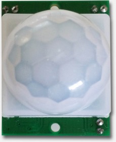
Cheap PIR – Top view
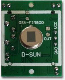
Cheap PIR – Sensor Exposed
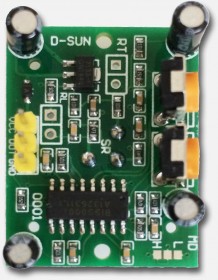
Cheap PIR – Bottom view
The short and simple explanation on how these sensors work
The sensor in the PIR detects or “reads” infrared radiation “emitted” from objects all around us.
Each object with a temperature above absolute zero ( -273.15° Celsius, -459.67° Fahrenheit, or 0 Kelvin) will radiate infrared, even us humans, and even though we mere humans cannot see this.
With special Thermal Infrared Camera’s however, this can be made visible to the human eye.
Note that the PIR just uses a relatively simple sensor – it is most definitely not a camera!

Example of InfraRed radiation
PIRs are called “passive” since they are not assisted by any “helpers” that for example would send some form or shape of “radiation” or “light” to help detect. It’s purely based on what the sensor can pick up out of the environment, what’s being emitted by objects.
PIR’s actually only look at the “difference” between two sensor “halves”. If the difference is too high then it will trigger – it detects “motion”. This is done in a smart way, to avoid false positives caused for example by a brief flash or an increase in room temperature.
A chip and some discrete electronics handles all this for you.
PIR Lens “Dome”
As you can see in the pictures above, the PIR has some funny dome-like bubble, which is a collection of lenses covering the sensor.
If you look closer, you’ll see that the “dome” is build out of little segments – each being a small plastic Fresnel Lens. These tiny lenses help the sensor to look “around” in one swoop, which would have been impossible with just the flat sensor (see figure 2).
PIR PCB
A few points on the PCB of the PIR are of importance to us:
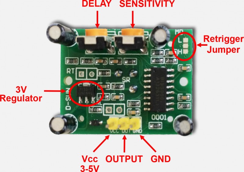
PIR PCB
The most important pins are of course Power supply (Vcc 3 to 5 Volts – it is said that this can even be up to 12V) and GND (Ground).
The OUTPUT pin is the switching pin.
The two potentiometers (orange) allow you to tune Delay time (Tx) and Sensitivity (Sx).
Testing your PIR
If you’d like to experiment a little with your PIR, or test how well it works, then you actually do not even need an Arduino or Raspberry Pi.
All you need is either a power source, a resistor and a LED.
The power can be drawn from either batteries or a power supply – 3 to 9 Volts will work – I used a 5V USB charger.
For the LED, we need to pay attention, since it’s important that we connect the pins right. The longest pin of the LED (Anode, or “plus”) should be connected to the resistor, see the LED drawing below.
The resistor should be 470 Ohms, the colors are Yellow, Violet, and Brown (see also the Tweaking4All resistor calculator).
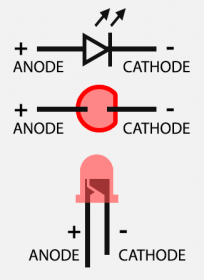
LED Pinout
Summarized:
Connect the PIR Vcc pin to the + of your power source.
Connect the PIR Output pin to one end of the resistor.
Connect the other end of the resistor to the long leg (Anode) of the LED.
Connect the short leg of the LED (Cathode) to the − of your power source.
Connect the PIR GND to the − of your power source.
And that’s all … you should have something like this now:
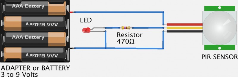
Testing your PIR with a Battery, LED and a Resistor
p.s. I made this drawing with Fritzing, a great tool to make electronic design!
Playing with the “settings”
Now that we have a test setup, time to do some playing.
When the LED goes on, motion is detected.
In the beginning you might notice some seemingly erratic behavior – this is perfectly normal. We need to understand a few things before we can tweak the settings.
When connecting the battery, the sensor will take up to 30 to 60 seconds to stabilize (warm up).
Place your setup in such a way that there will be no motion and wait until the LED remains OFF.
Once the LED remains OFF, you can move your hand or anything for that matter, in front of the little dome, and see the LED go ON and OFF.
Depending on what is moving around, the detectable range should be up to 20 feet or about 6 meters.
Also keep in mind that the sensor will remain “ON” for a little bit after it detects motion. At a later time you can tune the timing with the “Delay Time” potentiometer.
Delay Time
The “Delay Time”, determines how long the PIR will keep the Output “High” (ON) after detecting motion.
For example, when motion has been detected, you could set this somewhere between a few seconds (mine has an approximately minimum delay time of 2 seconds) up to a few minutes (specifications of mine claim about 200 seconds).
When assembling the basic test setup (above) and the LED seems to stay on forever, turn this dial down – the delay might be too long. The lowest setting, when facing the philips screw of the potentiometer, is all the way to left.
When doing your first tests, turn it as low as possible … until you notice there is a need for a time delay.
Sensitivity
With this potentiometer you can determine set the “range” you have in mind.
I have the impression that it regulates how much motion it takes to be “seen”, or maybe more technical terms: how much difference between the two “halves” of the sensor need to see before it’s considered motion.
You’ll have to play a little with this to see what is the appropriate setting for your purposes.
An increased sensitivity can be beneficial for when using a PIR for long range, say up to 20 feet (6 meters) or more. This can however also cause false positives in smaller spaces – i.e. the PIR might trigger when it should not.
A decreased sensitivity is good for a short range, say half of the maximum range or up to 10 feet (3 meters). Which in turn could miss movement at a longer range. Objects further away may need more motion to be detected.
To illustrate this, a little test …
First I did set the sensitivity to it’s lowest and walked 14 feet (app. 4 meters) away from the sensor. I had to wave both arms to get detection.
After that I did set sensitivity to it’s maximum setting and walked again 14 feet away from the sensor. No I pretty much only needed to move a finger to be detected.
Up to you to find what works best for your application of the PIR – with the test setup it’s easy to play and tune.
The Retrigger Jumper
On some PIR’s, they conveniently did not install the jumper (like in the ones I have) – this does not mean that they do not work. Just setting them is a little bit more cumbersome.
If your PIR does not have jumpers for this, and just soldering pads, then look closely and you might see that it’s default set to “H”. It took me a while to even see that mine was shorted to “H”.
The “L” setting seems to behave a little erratic – when you move in front of the PIR, you will see that it occasionally switches the LED ON and then OFF again. This is called “non-retriggering” – this setting does not or just barely retrigger.
When using the “H” (default) setting, you will see that the LED remains ON when moving in front of the PIR. This is what is called “retriggering” and it seems that this would be the most used setting as this seems to behave the nicest.
Additional Information Sources


Comments
There are 168 comments. You can read them below.
You can post your own comments by using the form below, or reply to existing comments by using the "Reply" button.
Hi,
What type of sensor is suitable for hands detection directly over the sensor? I would like to create a 5-notes musicial keyboard with 5 sensors, however I’m not experienced enough to know which sensor is suitable for this project.
Hung
Hi Hung,
The PIR would detect the finger, but if used for several “keys” then the other PIR’s would detect that finger or your hand as well – probably not something you’d want.
For your purposes you could consider a touch sensor (Capacitive touch).
I found this article at Instructables, which gives you and intro how to build those and work with those on an Arduino.
Hope this helps
hans
If I separate the 5 sensors 5-8cm apart so that it will just detect my whole hand to trigger the sound, it is still wise to use a PIR sensor or motion sensor? (Sorry new to sensors) Can I adjust the angle of detection for motion sensors? (since I just want the detection to be valid directly on top of the sensor)
As I want to show the “WOW factor” by making musical sounds without physically touching anything, hence I will not go into using touch sensor.
Need some guidance on this, thank you.
Hung
Sounds like the old theraminprinciple. Essentially it worked on a RF field and when you got closer to the wand the load on the RF increased. The circuit worked on having a sensor between the transmitter and the antenna. The closer you got to the wand the current sensed increased. That loading effect changed the pitch through another circuit the audible frequency modulator. Back then the sound effects in movies for especially weird sci-fy movies, such as UFO’s, were really ‘out of this world’ ha! The music of the rock and roll group the Ventures used a theramin for wild sound effects on a song or two.
dale
Can anyone advise? I have a pir sensor for a car alarm. The problem is that I turn the alarm on and immediately the alarm sounds. Is there a unit/board I can use to delay the “initial” power to the alarm but not to delay the the next activation of the pir? Many thanks
Matt Reade
Since it’s not clear if this is DYI alarm, or a commercial one, just some initial suggestions …
If you are using an Arduino, then you could have it (in setup()) loop until the PIR is ready (eg. switch “off”).
If your car alarm is commercial then you may want to contact the seller/manufacturer.
hans
Hi Hung!
If you want to keep things “touchless” then I’d start experimenting with PIR’s of which you limited the “view”.
For example, by placing a short tube or pipe over the PIR so the view to the sides are limited (just an idea).
Standard the PIR will have quite a view angle, which you’d like to minimize and this trick might work.
it will take a little experimenting, but as you can see above: creating a test setup is easy and dirt cheap.
You could even try the sensor by removing the little dome and possibly combine it with a short piece of tube or pipe.
Please let us know how your project is moving forward – it most certainly sounds interesting.
hans
Hi Hans,
One more thing, how many sensors can I plug into an Arduino uno? Are there enough to put 5 sensors and 2 speakers and 5 LED light strips?
Hung
Hi Hung,
that’s quite a lot, but I’m guessing the Arduino can do this …
5 sensors and 5 LED strips can be done with the digital I/O, the 2 speakers with the Analog I/O …
However … you might want to look at a larger Arduino, since the code needed to control all this might be too much for the limited memory of an Uno. So maybe look for an Arduino Mega or something like that.
Here a PDF describing the Arduino Uno pinout
hans
Hi,
you can use one Arduino uno R3 for 5 sensors + 5 leds + 2 buzzers or alarm devices. it will work fine. you can mix and match with digital and analog pins. However with your 5+5+2=12 components you can use all digital pins of arduino. you don’t have to write long codes for all just use Arrays and IF , else statements or you can you can use Switch/Case statements. those will minimize you codding.
Good LUCK
Arif
Hii
I made the motion sensor using This cheap sensor ,2 out of 6 sensor not working properly they work only when i tuch my hand on the potentiometer otherwise they not working what i can do . My setup is i use 5v supply with 1k register and bc547 transister and 5v realy. Please help me sir
Tejas
Hi Tejas,
Personally, I’d recommend contacting the seller and replacing the 2 failing PIRs.
(assuming these 2 do not work if you use the setup shown in figure 7 above)
Hans
Love the example above, with the battery and LED,
How can i add a on /off switch if i want to turn the led/or alarm off with the person/object in the PIR range.
i.e if a cow comes within the distance of the alarm and i want to turn it off with a IR Remote Control or a cord on/off switch.
Love some suggestions as im stuck and very new ot electronics.
Kuldip
Kuldip
Hi Kuldip,
I guess it depends on what you’d like to accomplish.
The easiest would be a simple straight forward On/Off switch between the + of the battery and the PIR board.
Of course this can be made much more advanced if you’d like to use a remote control (ie. smartphone, infrared, etc).
hans
Hi Hans,
As I’m going to paste a LED strip onto a rotating “mini londen eye”, the wires connecting the LED strip to the arduino will be tangled up at some point of time. I cannot mount the arduino onto the “mini londen eye” because the arduino is also connected to the sensors. Please advise.
Hung
Hi Hung,
I can see that to be an interesting challenge …
Option 1)
Wireless. Power the Arduino in the “London Eye” with batteries and connect to a computer or another Arduino using Wifi, Bluetooth, InfraRed or RF module.
Option 2)
Since the LEDs only use 4 wires, somehow make copper strips and contacts that slide over the strips while the wheel is turning.
Just the first 2 ideas that came to mind … I haven’t tried either.
hans
Hi, I have found a solution. By using a slip ring http://www.adafruit.com/product/736
Hung
Awesome! Didn’t know AdaFruit sells these … ready made and good to go!
Thank you very much for sharing!
Any chance you can share your project when it’s done? I’m really curious about what you’re building.
hans
Sure Hans. How can I contact you privately?
Hung
I sent you an email to the email address you’ve used for the comments …
hans
Hello Hans, does every PIR have approximately minimum delay time of 2 seconds to trigger? If that is the case, I’m not able to mimic a “music keyboard” as I need immediate response from the sensors. I have not bought any sensors yet, hence i’m still doing research on what type of sensors is most suitable.
Hung
Oh my goodness, I did not think about that …
A photo sensitive transistor/diode or and LDR might work better, or at least faster. Both options are cheap too.
But you’d need to assume that there is light coming on those sensors, unless a hand or finger is positioned above the sensor and light is being reduced.
So at startup you’d need to gage the initial value (which might not be 100% stable with an LDR), and respond when you see it change more than a certain percentage.
Photosensitive transistors/diodes might be a little trickier to implement though because the simply are ON or OFF.
An ultrasonic sensor might work very good as well – I found this article discussing a few options, including an option I did not think about. But they might not work as you’d like them to work.
There are quite a lot of different sensors out there, I did see this Arduino Forum topic discussing a short distance sensor.
Mouser, a well known component distribution company, has quite the list of components that could help.
A sensor like the Leap Motion Sensor would be pretty impressive and cool to use – however, I doubt it’s usable with Arduino and it might take a lot of time on your end to get to to do what you’d want. You’d need only one sensor, but it doesn’t come cheap ($80).
hans
Thank you for the links. I could not use photo sensitive transistor/diode/LDR as my project consist of LED lights strips that might affects them. And I will switch off my rooms lights and play with sensors, so it’s like a very dim dark room.
I read the links you gave and found a Sharp GP2Y0A21YK IR Proximity Sensor. They said that this Sharp Sensors has capability up to 150cm range detection, which is really nice. Will the lights from my LED light strips affects the IR sensor readings? Will those sensors work after i switch off my room lights?
Hung
I read about that one too. I am however not quite sure how “far” away you’d like hands or fingers to move.
The reason why I’m asking is that if the area to move in is too narrow, then sensors might overlap each other. I have not tested these sensors but I can imagine that a longer distances it’s “beam” would widen, like in a V shape.
I honestly have no idea if regular LEDs would interfere, but I would guess not.
Did you look at the components at Mouser – they seem to have some pretty interesting ones.
hans
@ Hung … Removing the fresnel lens may work for a musical instrument as it reduces the detection angle considerably (check the PIR spec sheets) and you could always go with the smaller PIR’s too
Just search ebay for mini pir
Bob
Thanks Bob for the tip!
hans
can a PIR sensor detect the motion of a object moving before 2-10 centimeters?…if not what is the minimum distance it starts working from?
sam
Hi Sam,
I would think it does detect that yes. I suppose it also depends on the object (size and type of material).
The specs of some say “up to 20 feet” and do not state any minimum.
hans
Whom it may concern,
I am Rara who is working for company which provide golf swing motion sensor.
We outsourced creating motion sensor, but often time occurred errors, so I am looking for company or people who is capable of analyzing our motion sensors, find out problems, and fix the errors.
Thanks,
Rara
Rara Jeon
Hi Rara,
Even though this is not the place to post such a request (the forum would have been better), if anyone feels an expert to help, then please feel free to post a reply here.
hans
Hi,
Great article! i’m very new to this electronic stuff and this got me started real good.
I have now succesfully build a little alarm with a 433mhz remote control to switch it on and off
One question, do you know a way to prevent the pir from triggering at startup? I’m not using any IC’s just plain components.
Regards patrick
Patrick
Hi Patrick,
Thank you for the compliment
Well, without making it too complicated, you could add a delay of a couple seconds when “arming” your alarm or powering on the Arduino (in setup()).
I do recall a PIR taking a few seconds to “calibrate” when you fire it up (ie. power the Arduino).
So a “delay(3000);” (3 second delay) in setup() could do the trick.
hans
Hi Hans,
Thanks for your quick reply. The challenge for this project was to use only simple components, so there is no arduino or pi involved. Was hoping maybe there was some sort of trick to prevent the trigger. I will see if i can find a schematic for a delay.
Thanks anyway!
Patrick
Oh sorry, missed that point, doh! .
.
Lesson learned; never try to answer a question when you just woke up and have not had coffee yet
I think the challenge would be that if you add a delay, the delay might be over the PIR, causing it to always delay. Probably not what you’d want.
Maybe you’d need something like this, just the reverse version, so instead of make, a break contact, which disconnects your alarm indicator for the first 10-60 seconds after powering on your device.
Please post your solution of you found one though!
Others might find this helpful as well!
hans
you are right about delaying the pir itself, that’s what bugged me indeed. That link might be just what i need. I will first try to wrap my head around it
I’ll keep you posted on the progress…
Patrick
Awesome! It would be interesting to see what you come up with!
Does the alarm have something like an LED lighting up or Siren going off?
You could think of “disabling” that for the first minute, even when the PIR signals there is motion, prevent the light or alarm from going off.
hans
Hi Hans,
That was a good idea to disable the buzzer…!
I’ve found this circuit, and after fidling around with the values I have put this in front of the buzzer, delaying it for 40sec before it is able to react to the PIR’s signal.
works like a charm!
https://www.youtube.com/watch?v=GeveeSTyvGs
Soldering the lot on a little board, and on to the next project!! thanks!!
patrick
Awesome!
I tried finding the schematics, so I could post it here, but the screenshot of the video is kind-a hard to read. (no problem if you do not have one).
If you do have a drawn schematic, please let me know, so I can post it here
hans
from Patrick:
Took some time, but here is the schematic, (kinda… I drew it myself). I have placed this in front of the buzzer so the transistor ( a BC547) acts like a switch for the buzzer.
Once the capacitor is saturated, after approx. 45sec it will make the transistor conductive, allowing the PIR to sound the buzzer.
So now I have your PIR test circuit with a transistor sounding the buzzer. The PIR is powered through a latching circuit based on a 555. The latching circuit is triggered by a 433mHz receiver, using the linear output, supplying a pulse to trigger the latch.
It is my first circuit, and I’m pretty proud too..!!
Thanks again for your kickstarting this.
hans
Awesome Patrick!
And … thanks for sharing your solution – it’s the kind of solution I had in mind as well, just didn’t know the details of the schematic yet haha … nice!
hans
Great article! One question… how do I know what resistor is suitable for the PIR if it does not state anywhere what is the expected current. My PIR looks exactly like yours. Do I even need to put a resistor? Thanks!
David
Hi David!
Thank you for the compliment! That’s always appreciated!
As for the resistor; it’s only included to protect the LED. Most LEDs these days seem to be able to survive without a resistor, but it’s probably better to include it anyway. 470 Ω is a common value for it.
hans
Thanks Hans! I’ve got my setup all working now :D
David
Awesome!
hans
Dear Hans
I’m so glad to read your this article ,
I’m confused about how to test PIR’s exact range , for example : The detect degree range of horizontal and vertical direction. I know we can get the a rough results by body moving . However we need a very exact test reults for different distances(eg: 1,3,5,7 meters) . Do you have any good ideas to help me implement a good solution for get exact test results ?
Thank you very mych
Jim.Gong
Hi Jim,
I agree that the range (directions/distance) are a little “soft” and definitely difficult to tune if needed.
The only way I know to properly determine the coverage range of a PIR is by simply testing one setting at a time (which is hard with the potentiometer on the PIR). It’s kind-a the same issue one would have with PIR’s that come with conventional alarm systems as well. It takes a bit to tweak it to the right sensitivity.
So, sorry that I do not have a cookie cut solution or answer to your question …
hans
hiii. i got the delay in the operation of PIR On & Off. Actually i dont attached any delay in programme still the led is not change its position for around 4 seconds of operation. can u suggest me some solution for it?
thanks in advance…regards,Mohak shah
Mohak
If you mean that at startup, the PIR takes about 4 seconds to “warm up” then I would not know a work around for that.
The PIR has to adjust to it’s environment when powered on, which takes a few seconds.
hans
Dear Hans, My name is Ashish and I am doing some research on Intrusion Alarm Systems, a typical kit includes Smoke sensor, PIR motion sensor, Door sensor, siren and host panel.
There are companies who sell such systems for 300$ and then there are who are providing it for 30$!! I understand that a lot of factors come into play; however given that the technology have been around since quite sometime and there so much one can do to improve the results, why such price variation?
I can procure PIR sensors from China at 2 $ a piece price , the same PIR sensor from Honeywell will cost me about 20$ !! Is there really a huge difference? or any difference at all (except the battery life may be! )
The reason I am asking these questions is because I am getting a complete product KIT customised from a Chinese company to offer the security solution in service based model.
If possible and if you have some spare time, can you provide me your email address? I would like to explain more about the kind of customisation I am getting done and technical challenges I am facing and would like to have your expert opinion.
Regards
Ashish
Ashish
Hi Ashish,
I woud assume that there might be a difference in quality, but it might also depend on wether or not there is a case around it.
I’ve played with $1 PIRs and they work just fine for me. I also tried a more expensive ($150) PIR, the difference being that the expensive one had a nice case around it.
You might have to test a few to see if there is a significant difference. I couldn’t see a difference between the 2 I tested (the $150 went back to the store hahah).
hans
Thanks Hans for taking time and answering my question. This is really helpful, cause I know that we can take a chance with cheaper PIR sensors (yes we have to test them properly! )… Really appreciated.
Do you also get involved in Alarm panel to CMS communications area.. there are many ways and many protocols, and I am quite confused with all that… and wondering if you can help me there as well?
Ashish
You’re most welcome Ashish
As for Alarm panel to CMS communication; I’m considering starting a project like that but I will have to do a lot of reading up before I can answer any in depth questions … sorry …
hans
Thanks Hans, its good to hear that you want to start a project in this area. If you need any help to understand the available technologies, methods, pro-cons etc… let me know, I have done a lot of research …although i am still confused with some of the protocols.
Regards
Ashish
Ashish
Thanks!
I’m in the middle of a move (to the US), so it might take a bit before I get to it …
hans
I have a 230 volt PIR. I use the trigger line to operate a relay. My problem is that the trigger circuit is not at zero volts when the pir is not detecting an intruder. The voltage on the trigger wire varies over time and this in turn triggers the relay randomly. How can I prevent this? (12 volt PIRs overcome this problem but cost some £65)
edward
Hi Edward,
I have no experience with 230V PIR’s, and I’m not the best guy in electronics either …
…
First of all, the PIR’s I use costs $1 at eBay or AliExpress, when I bought 10 at a time. Worth looking into?
Second thing to think about might be something like a capacitor … I’m not an expert, so I’m not sure if such a filter will do what you want.
Now as far as the signal goes; if you’re using something like an Arduino, you might be able to catch this in code as well.
I am however wondering how your PIR would normally be used …
hans
This article on bypass capacitors might be helpful …
hans
Hi
Can a PIR sensor can be adjusted to sense humans maximum at a distance of 10 – 15cm?
If not are there any sensors to do so?
Also are there any sensors (PIR or any other) which has a straight constant width detection range and not increasing for the detection of humans?
ABHISHEK GUPTA
Hi Abhishek,
I’m (of the top of my head) not aware of any PIR sensors that meet your specific demands.
What you could try however, is remove the plastic “dome” around the sensor. It will narrow down the width.
hans
Thanks for your answer,
Are there any other sensors which meet my demands?
ABHISHEK GUPTA
There probably are, but honestly; I have no idea which types/models … sorry
But: please post here if you find any! I’m sure others might be looking for that as well. I just had not had the time or need for it.
hans
[…] and timing potentiometers marked on the back, so I had to look at a whole bunch of other models/examples and kind of fiddle until they worked. I also included an LED that would let me know when the camera […]
When there is a motion LED is on. but when there is no motion, it turns the LED for about 5 seconds and after about the same time it turns it off. This happens always and periodically when there is no motion? what is wrong?
saeid
Hi Saeid,
Either your sensor is faulty, or it is set to an oversensitive setting, or … something in it’s line of view is actually moving …
hans
Thank you. But I checked with 3 sensors all have the same problem. I checked with different sensitivity but still have the problem. I am using Adafruit Huzzah. any suggestion?
saeid
I have never used the Huzzah, but it sure looks interesting!
I don’t think this conflicts with using a PIR though, but to make sure you could make a simple setup (as shown here) to see if the bad behavior of the sensor still occurs … this way we would eliminate influence(s) from the Huzzah.
hans
Hans, Have you ever heard / knew if domestic lizards may trigger the PIR sensor?? Domestic lizards can walk at any surface and I won’t rule out the possibility of them walking over the sensor itself.
If that is indeed the case, how can we avoid that?
Ashish
Hi Ashish …
Hahah well, that’s an interesting problem indeed …
…
You could build a cage around the sensor from, for example, chicken wire or something like that.
Enough holes in it to detect motion, and since the chicken wire cage is not moving, the sensor will not “see” it.
Hopefully that keeps the lizard out …
hans
:) :) :) That’s indeed good idea, I will consider it if I face this issue in real life :).
Thanks
Ashish
Ashish
Hello Hans,
I am in serious trouble here, I tried to use PIR with raspberry pi for a project to detect motion and the sensor is detecting the motion but the problem is that it also triggers without any moment when faced towards wall with some distance. It keeps triggering two times in each minutes like in 6th second and 51th second in each minute continuously. And the problem is I don’t have other pir sensor to test with and the cheaper one comes with around 10$ for each with minimum of 2 day of delivery . So I want help as I am absolute beginner for these sensors. Please help here.
Dilip Poudel
Hi Dilip,
You could try changing the sensitivity, and see if it improves the situation.
Additionally, either the PIR is defective (which I have not encountered yet!), or there actually is something triggering the PIR. Keep in mind that heat sources and critters can trigger the PIR as well.
Another reason that might trigger the PIR is a not so stable power supply (effectively resetting the PIR).
Also note: if you buy a 10-pack, for example this one at Amazon, then the price of a single PIR drops well below $2.
hans
Thanks Hans,
I got it okay now , Once I changed from PI 3B to PI 2B it worked just fluently and I came to conclusion that the PI 3B with a PI NOir camera with IR lamp attached to it can’t provide enough power to pir sensor as it is more power hungry. So if any one have come across such problem it is not on your sensor its the problem with PI 3B which takes too much power source and the normal adapter can’t deal with the PI 3B. And sorry Hans but the Amazon can’t deliver in my country (Nepal) and yes I think we have to pay double the amount for these machines for atleast few more years. 10$ for sensor 68$ for pi and around 52$ for sainsmart 5mp camera but still pi is pi just amazing to explore.
Dilip Poudel
Hi Dilip!
I’m happy to hear you’ve got the issue resolved. Nice! And thank you for posting it here as well!
As for thing being expensive in Nepal: Oh my, and I though I had it rough when I was living in Holland (expensive shipping, and Dutch customs charging an arm and a leg on import and sales taxes). I’m sorry to hear that – maybe countries should look a little closer to the rules they dictate when it comes to electronics like this. It’s preventing others from developing innovative things …
hans
Hello,
can anyone tell me what is the minimum difference in IR needed by a PIR to be triggered. I am thinking to use it to detect movement of small insects that emit a tiny amount of IR.
Thanks!
Matteo
Matteo Marcantonio
Hi Matteo,
I would not have an idea how much change in IR would trigger a PIR, but you can set the sensitivity and experiment with that to avoid false positives because a bug happened to walk by.
hans
Thanks Hans,
this is encouraging, I will definitive get one and test it modifying the sensitivity, thanks!
Matteo Marcantonio
There is diode in the circuit, so you cant feed it using 3.3v, because the voltage will drop to 2.7. If you want to use 3.3, just remove diode and short it, also jumper from vin to vout in regulator.
yudha
If in front of pir sensor the small object moves then pir work or no….plz expain me in detail…..
ashu
Hi Ashu.
Ehm, I have no idea what you mean?
hans
Hey,
I have the task of checking weather a person would be available at his cubicle/desk or not. This is to be achieved by using the application of IoT and raspberry pi 3. As i shortlist my possible sensors, PIR being the front runner, I wish to position my PIR sensor below the table. Thereby detecting the IR emitted off of the person close to the sensor. However, I had a few concerns regarding the sensitivity, and if it would be more effective in the given application without the fresnel lens(given that i require it to be unidirectional). Also, I’m open to suggestions regarding the usage of PIR. Needed a second opinion on this.
Thanks much
Varun
Hi Varun,
I’m not sure if a PIR would be the best sensor for your application, as it detects change in “heat”. So if a lazy person would be sitting still all day long, your sensor would probably not detect this person. Then again, it’s all a matter of testing …. (ditto for the sensitivity and using the lens yes/no)
Also, if you intend to use this for multiple cubicles, and you’re looking at an IoT approach; consider using ESP8266’s instead of a RaspBerry Pi. The can be used as an Arduino with WiFi right away build in and they are less than 1/4 of the price of a Raspberry Pi. (example link: Amazon).
hans
Hi Hans,
Thank you for the timely reply. Would you have any suggestions regarding which sensor to use to improve the result of my use case . Also, according to my knowledge, the PIR sensor detects difference in heat between two given points. I was hoping to use this principle, that is “When the sensor is idle, both slots detect the same amount of IR, the
ambient amount radiated from the room or walls or outdoors. When a warm
body like a human or animal passes by, it first intercepts one half of
the PIR sensor, which causes a positive differential change between the two halves.”, which like you said can only be perfected using intensive testing. Your thoughts ?
Also, is price the only advantage of the ESP8266 as compared to the raspberry pi ?
Thanks much
Varun
Hi Varun,
Of the top of my head, I would not know a simple to implement alternative. I would however test the PIR first before concluding that it won’t work. I have not tested this and I would assume that it will be very hard for a person to not move, additionally add some logic to your code that assumes nobody present in the cubicle when there was not motion detected for say 20 seconds or a minute. Again; testing will give you an insight in what would work best.
I would say that my reasons for the ESP8266 would be: price, size, and simplicity. Arduino like devices would not need an SD card with an operating system, and the operating system would not as easily corrupt. It will also “boot” much faster. Considering your purpose, I’d keep it simple and as stable as possible …
Hope this helps …
hans
Hi Hans,
Thanks a lot. That was quite helpful.
One more thing I’d like to know, was on how to go about to increase the time delay required for the pir sensor to switch the circuit off once it does not detect motion. This would be required in order to improve efficiency in terms of the output. Would it help if I connected two Pir sensors in parallel to detect motion, thereby improving my output ?
Regards
Varun
Varun
Hi Varun,
glad to hear it’s helpful.
I’m not understanding your question – You mean “shutdown” the setup, for example at night when there is nobody in the cubicles?
hans
I am doing my project using pir.
The problem i am facing is that i am giving an input to pir of the order of 5-7 volts but at the output i am getting very low voltage which is not even enough to glow an led even without uusing a resistance
I have 4 pir but all behaving the same
Please help me
ayaz
Hello Ayaz,
you should see the “output” pin as a switch pin. When the PIR is triggered, power from Vcc (left of the output pin, connected to the “plus” of the battery) will be directed through the Output pin, supplying enough power for example for an LED. The other pin of the LED is connected to GND (in this case: the “minus” of the battery).
Study figure 9 (above).
If this is what you are already doing, then consider trying another PIR – yours might be faulty.
Hope this helps.
hans
what is the IEC or BS standards that you used to test the PIR motion sensor
manu
Hi Manu,
I did not follow any IEC or BS standards. Any specifications mentioned are manufacturers specifications.
hans
Hans,
I wanted to test pir sensor with an IEC or BS standards but don’t know how to get the correct standard for that. Do you have any suggestions?
Manu
Hi Manu,
apologies for the late reply – regular work has been dominating my daily life the past weeks.
Since I never use any of these standards, I wouldn’t be able to make recommendations which one(s) to use
hans
Hey, can you explain more about the adjustment knobs?
Thanks in advance
Daniella
Hi Daniella,
what additional information are you looking for?
One is the time Delay; or how long the PIR will keep the Output “High” (ON) after detecting motion (how long will it flag a change as “ON”).
The other one is for Sensitivity, or how sensitive (by changing the range – or how far it looks) it is to motion.
hans
Hi,
Can I use PIR sensor to detect the objects like crinkled paper.
whether PIR sensor detect those kind of object.
Karthikeyan
Hi Karthikeyan,
unfortunately, that is not what a PIR was designed for. Sorry
hans
Hi
Can you please tell me how to add a voice message instead of an LED light ? So that when someone passes by it will trigger a voice message
Hakeem
Hi Hakeem,
I have yet to play with Audio and the Arduino, but maybe a project like this one (Arduino Audio) might get you started.
The Arduino website also shows a project that helps you create audio on an Arduino.
Some more examples:
– Arduino PCM Audio,
– PWM Audio with a Piezo,
– Instructables – Simple Arduino Audio Player
hans
Hi,
Actually we have our own design for
the PIR Motion sensing but it isn’t working properly,
so can you send any reference design for the RE200G sensor(Schematic
and Board design)
In our prototype,it is found that the angle of detection is less than 50 degree,can anyone help how to take care about this while designing using the PIR sensor,like placing the PIR Sensor(On which layer of PCB)LIKE THAT.
Sindhu
Hi Sindhu,
not sure if anyone here can help with that. A quick Google did not give me much info on your question … sorry
hans
Hi,
is it possible to set a range for your pir of how far you want it to sense
Emily
Hi Emily,
You can kind-a set the “distance” with the sensitivity dial – but it’s not very accurate and technically not for setting the distance – more so for how much change needs to be seen before it is seen as motion detected.
hans
Hello,
I am having problem with association. Please HELP ME: I have associated my lights with my PIR sensor so whenever it detects any movements it opens up the light but after 3 minutes it closes it. Now my problem is that when this PIR sensor closes the light then it didn’t come back to its normal position till 3 minutes and after 3 minutes it again start detecting motion. like for example> i went to my washroom motion sensor detects me and opens up the light but after 3 minutes it closes it since i am in the bathroom so i wave it towards motion sensor so that it reacts again and open up the light but it didn’t till a few minutes then reacts and opens up the light. What should i do?
Mac
Hi Mac,
you’ll need to implement a delay-off timer.
This goes beyond the scope of this article … but you can either design one, or buy specific modules for it (like one of these or one of these). For example this module is only $3 and can delay 220v 0-99 minutes.
hans
Hello. The distance between my pir and my alarm is too far for the signal. Is there a way to create a device to go inbetween pir and alarm? thank you for your article
Andy P
Hi Andy,
I’m not 100% sure what you mean, but if you mean that the wire from PIR to Alarm is too long and the signal degrades too much, then you may want to use a transistor to “boost” the signal.
I did find an example at StackExchange. Here they use one or more transistors to “boost” the signal from 10mA to >200mA and even 1A.
Hope this helps.
hans
Thank you.
My pir alarm is wireless. The distance between point a and point c is too great so was hoping to find something to go at point b to bounce the signal from pir to the alarm box across a greater distance than they are designed for.
Thanks for your help.
My idea is to take a second alarm box and remove alarm sounder. Attach the signal sender from a spare pir in sounders place. Creating a middle distance receiver and sender in one. Does this sound feasible to you?
andrew
Hi Andrew,
What type of wireless signal is being used? If it’s a radio signal (eg. WiFi, Bluetooth, 2.4Ghz RF, etc), then you could consider increasing the size of the antenna.
I’m not sure if this is a homebrew alarm (allow more modifications) or a commercial alarm (making it much harder).
Setting up a “repeater” (as you suggest) may work as well, but … I wouldn’t label it as the most reliable way to do this and you’d need to know details about the wireless signal, so you can make a receiver and a transmitter (the “repeater”).
hans
does the PIR sensor help me detect a motion and follow it all the time.. I have a project that i have to make a robot that detect a motion and follow it
rebecca
Hi Rebecca,
a PIR will not be able to “follow” any object. It just detects that there is motion, not where or in what direction it may be moving.
So I don’t think a PIR is what you’d need for your project, unless you use multiple PIRs and even then I’m not sure it will be useful for your needs.
Here is an example project trying to follow motion with 5 PIR’s …
I think using Ultrasonic detectors may be better, but I haven’t played with those yet. See this example project.
Hope this helps…
hans
Hi hans,
Thank you for your help.
I only have one question left… if something pass in front of the pir can we know the position of it in the range of detection… (like if i m standing in front of the sensor is there any code that can say that i m 20 degree right the center of detection of the pir?)
Rebecca
Hi Rebecca,
you’re welcome!
As for your question; under normal circumstance this is not possible with a PIR. To detect something like that you’ll have to combine multiple PIR’s each with their own “viewing area”, so that when certain PIRs trigger, you’d “know” that you’re roughly in that position. I’d recommend reading that example project where multiple PIRs are combined, which will give you an idea of what I’m talking about. In this example you’ll see that the designer created a “tunnel” or “view” for each PIR by using walls between the PIRs.
hans
Hi,
I would like to know if a PIR can be replaced on a trail camera that a company stated the components are proprietary? The cameras just came out of warranty and the issue is that they continually take pictures once triggered. The company customer service person stated it was probably a corrupt PIR and the company does not have a repair shop anymore so I should just go and buy new ones. I have taken apart the trail camera and seen where the PIR is but cannot get any info from it as a part number. It has 3 pins. I was wondering if a generic PIR or another brand would work? Right the cameras are useless and pretty sure these are “fixable”, certainly do not want to buy more trail cameras, especially from this company again. thanks
Rick
Hi Rick,
well, I’m pretty sure there are several different models when it comes to PIRs. So the short version of the answer would be: I don’t know.
The longer answer would be;
I can imagine that they have used a cheap PIR like the one shown in this article. Since the camera is already useless at this point, you could try one of the ones used in this article – I did see a few at Amazon for about $8 for 5 PIR’s.
You may run into 2 scenarios;
a) they used a little board like the ones you have seen here, or
b) they sensor (the metallic round item with a square on it – kinda looks like a transistor) is fixed on the main PCB of the camera.
In scenario A, you could try to determine what the 3 pins in the camera are. One pin is ground and another is power (typically 5V). Whatever pin is left would be the OUT signal of the PIR.
Scenario B maybe a little trickier; you’d have to remove the sensor of the cheap PIR’s and solder them into the camera. Finding the pin layout may be challenging though. I think the sensor itself has 3 pins as well.
hans
Thanks Hans,
The PIR is on the mail PCB of the camera and looking at the back of the board it looks like a 3 pin (solder points). The only thing is that this PIR looks to be 2 parts. The top part is like the one on this site in Fig 2 and it is 6 mm in wide and there is a black part on the bottom that is 7 mm wide, the height is 1 cm in total; 3 mm is the silver part like the one in fig 2 of this site. Not sure what the black part sitting under the PIR is though?
Rick
Rick
Hmm, that is kinda hard to judge without a picture. (feel free to email me at webmaster at tweaking4all.com) .
.
Not sure if there are PIR’s out there that utilize 2 parts – then again; I haven’t seen all of the possible variations either
hans
Hi Hans,
Sent you an email with the pics as requested
thanks
rick
Hi Rick,
I did see your email and the pictures and replied. For others following this;
The sensor looks similar to the one in the cheap one I’ve used in the article.
The rectangle spot (detection area) is a little bigger than the one I have though.
So you could try swapping them out and see what happens.
I suspect the model in your camera may be a little more sensitive than the cheap ones though.
When swapping them out, you may want to use a multimeter to determine ground and +5V – just to make sure the pin-out is the same. When removing the current sensor (I honestly have not seen one get broken yet); you may be able to see the sensor type and number, which may be helpful in finding a replacement.
hans
Hi
I have PIR with 4 JUMPER settings-1}LED on/off 2)TIME 5sec/5 min 3)DISTANCE high/low and 4)PULSE off/on. In which position the PULSE jumper is to be set?Is it to be put in OFF position or PULSE position? And why?User guide that came with the device says “Turn on/off two way communication feature”
Thanking you
Dr Ramesh Rao.
RAMESH RAO
Unfortunately, I do not know the device you’re using.
I just replied to your email as well, but had not read this comment yet.
I suspect this feature is used if paired with an alarm system (set it to ON). Not sure why they’d even have a separate switch for it.
hans
Thank you anyway.It is a PIR supplied with D3D WI-FI SMART ALARM SYSTEM.Marketed in UK/EUROPE,ASIA and AUSTRALIA and USA+CANADA according to the brochure.Probably manufactured in CHINA.Bought it in Amazon.in.Not much information online.I assume you have seen the photo of the device sent as an attachment in the E-MAIL.
With Regards
Ramesh Rao
RAMESH RAO
Hi Ramesh,
I received your email and replied. I’m just replying here as well for others to see the response.
I suspect the PULSE jumper needs to be set to ON in order to communicate with the Alarm system. The manual (picture) doesn’t say anything useful about it.
hans
Hi Han
Yes,I bought a HOME SECURITY SYSTEM consisting of a CONTROL ALARM UNIT, 2 DOOR SENSORS and 2 PIR SENSORS.PIR sensors triggers the ALARM UNIT in both the position of PULSE switch -either OFF or ON.It communicates in both the position.I could not make out any difference.Hence all these my questions and queries.
With Regards and Respect
Ramesh Rao
RAMESH RAO
Hi Ramesh,
sounds like your alarm system has PIR units that can be used for other purposes as well – and the manual most certainly is far from clear or complete.
Good news is that it works either ways for your purpose haha. But I do understand your confusion – I wouldn’t know what to think of it either.
Kind regards,
Hans
hans
Hi Hans
Thank you.If I come to know anything more regarding PIR from other sources,I shall let you know.
Thanks
Ramesh Rao
RAMESH RAO
Thanks Ramesh, sorry I couldn’t be more helpful.
hans
Hello,
I’ve a small query if anyone of you can help with. Recently I bought PIR sensor from online market. This is the first time I’m dealing/learning electronics. PIR sensor contain BISS0001 chip which has 16pins. In my case pin 1 and 2 are soldered together. I’m thinking to attach this with arduino board to make a project but I’m not sure if this will cause issue as pin 1 and 2 of BISS0001 are soldered together.
Will it cause issue if I use this PIR or I should buy new one?
Thank You in Advance
Raghu
Hi Raghu,
sounds like it’s using the same chip as the PIR in this article. I’m not sure if pin 1 and 2 will be problem – you may have to take a look at some of the schematics out there (Google).
hans
HiI made the exact connections as mentioned in this article,but the light doesn’t seem to turn off. It always stays on. What may be the problem? Kindly respond. Thanks in advance!!
Vishal
Hi Vishal,
there can be several reasons why the light remains on.
A simple test could be: cover up the PIR with for example a towel.
Switch the setup ON and wait for about a minute.
If it still stays on, then there may be something wrong with the PIR, the wiring, or your PIR has one or the other jumper set wrong.
hans
Hi Hans,
I actually have set the settings to the lowest(turned them both completely to the left). I also waited for more than a minute to allow the sensor to get used to the environment. I did the test you had suggested with the towel,but to no avail. It still remains on. As for the wiring, I have given them right. I can perhaps send you the pictures via email,if you provide me your email. I’ve given the jumper(trigger) connection to high and the middle pin. I’m working on a home automation project with arduino and pir sensor, so this component is of utmost importance. Maybe the sensor is defective.
Vishal
Hi Vishal,
If you have more than one PIR available, then please test another one (they are very cheap after all).
It sounds to me that the PIR is defective – but I could be wrong of course.
hans
Thanks Han, great article. Is there any way I can detect if someone is approaching or walking away using a PIR sensor? Is the voltage output from the PIR sensor a function of distance? ie. I’m looking for a way to not only detect that there’s motion, but also to detect if that person is moving toward the sensor or further from it.
Thanks!
Beraa
Hi Beraa,
That is an interesting question … as far as I recall, the PIR by default only triggers (eg. On vs Off) and therefore does not indicate something like a “strength” which could indicate distance. This doesn’t mean the actual sensor on the board cannot do this – I just don’t know (I do suspect it does internally use some sorts of signal strength and triggers if it exceeds or drops below a certain level).
What may be a better solution, but I haven’t looked much into this yet, is using an Ultrasonic sensor. This may be worth looking into.
hans
Hi –
Is there any way to boost the power coming from the PIR, or to add power to the object it’s triggering?
I notice that even with 9v powering the PIR, the power it supplies to a standard white LED is pretty low.
Thanks –
Andy
Andrew
Hi Andy,
yes there are methods to amplify the signal. Both may require a little research.
Option one, is by using one or more transistors – this StackExchange post is a very good read on this method.
Option two is maybe easier. You could use a cheap Arduino. Have the Arduino read the PIR signal, and with code have it switch a relay.
This example and This example at Instructables for example even allows you to use 220V.
Arduino’s can be found very cheap, and the same goes for relays that can be used with the Arduino.
Hope this is helpful.
hans
hi,
can I need to now the particle distance range value in both horizontal and vertical direction
csr
Hi CSR,
unfortunately, a PIR will not be able to provide you that kind of information.
You’ll probably need something like an Ultrasonic Sensor (for example this project or this project).
Sorry.
hans
Hi, i implemented my pir sensor manualy to a 12v bulb, but instead of lighting up upon detection it turns off and when nothing is detected it is on. How can i change this high/low diference?
Sam
Hi Sam,
That’s a little different than what I have seen with my PIR – it brings the OUTPUT to HIGH when motion is detected. Your setup suggest the opposite (LOW when motion is detected). Not knowing how you connected things, I can only say this;
Personally I wouldn’t connect a 12V bulb directly to a PIR, rather use (for example) a relay in between. A 12V bulb may be too much for the PIR to handle.
As an option you could use a relay. Depending on the relay there is the option to have it switch ON when there is power on the relay coil, or switched OFF when there is power on the coil (usually this is a toggle switch within the relay). So this would allow you to use the PIR either way.
Again, I don’t know your setup, type of PIR, etc. The relay trick would always work though, but I suspect there is something else going on.
hans
Working on a project, I need the PIR to sense heat and not go off but instead when there is no heat for the alarm to light or send a signal. I want the entire board and battery pack in a metal box that will be placed close to the car exhaust and heat up while the car is running but then it cools when the car is off and box cools and sets off an alarm or send a signal. So very very new to all this and need much help a lot smarter than me., Thank you, Pat M.
Patricia
Hi Patricia,
A PIR will probably not be suitable for this purpose.
There are alternatives though;
Option 1 – Use a sensor
At first I was thinking of using a temperature sensor (like in this article).
However, the sensor in the article mentioned has only a range of -55°C to +125°C (or -67°F to +257°F).
Reading this article How does hot an exhaust gets show me typical temperatures (when “hot”) between at least 300°C to 500°C (570°F to 930°F) and this article states similar temperatures (I’m guessing they talk about temperature in degrees Fahrenheit). So this would be too hot for the sensor (not sure what will happen to the sensor when temperatures are too hot).
So we’d need a different sensor.
This page shows us we’d probably need a thermocouple temperature sensor.
As far as I understand, you’d need an amplifier (like this one from AdaFruit – they also have a few example projects utilizing this sensor).
Caution: A battery is something I would not put near the exhaust – the heat will likely damage the battery (if it doesn’t burst or explode).
So I’d install the sensor on or near the exhaust, and have a wire run into the car where the Arduino, LED and battery are located.
As for the code; I’d set a threshold. If a detected temperature is not at least X degrees: LED on, else LED off. This would work for the 2nd solution as well.
Option 2 – Use the OBDII interface of your car
Having said all that, depending on the age of your car: your car may already have a sensor in place to detect the temperature of your exhaust – which possibly could be read through the OBDII interface. This may be the way to go, but you’d have to do some research on the needed OBDII code for your car. I’m not sure why you need the exhaust temperature, so this may or may not be suitable for what you’re looking for (I assume you want to know when it’s “at temperature” to floor it haha).
Obviously this has some advantages, if this works for your car:
You wouldn’t need to install anything under your car, no worries about overheating your Arduino/Battery/Sensor, right away the correct sensor, easier wiring, etc.
Granted: it may cost a little more (you’d need an ELM327 to connect your Arduino to the OBDII connector in your car, typically located under your dash somewhere).
Some example projects that connect the OBDII to an Arduino:
Arduino Forum, and the same project here again on ArduinoDev in more detail. This module can be purchased, or you can do your own ELM327 hack.
SparkFun has some gear for this purpose as well, but their approach seems more complicated (number of items needed), but they do have an interesting guide to read.
Again: You’ll have to determine what the OBDII code is for your car and which part and what info of the exhaust you’d like to see what kind of info from.
A long list of OBDII codes can be found at this Wiki Page – your car may have more codes available than listed here.
By the way; if you do not find the right OBDII code, you can (it seems) add your own: see this YouTube video.
Hope this helps to get started
hans
WOW!!! Such a prompt and very understandable answer. OK, I have to give you more. In the project, I need to know when the car’s motor has stopped and it will get a timer started. It will also know when the car is running which will stop the timer. Thanx Pat
Patricia
You’re welcome
First off: I did see that I made a typo in my text. The car interface is called OBDII (and I just kept typing ODBII ) – I corrected the text above.
Anyhoo – if you decide to go to OBDII route, then you can read the RPM of an engine from the OBDII data as well.
If the RPM = 0 then the engine is not running. If the RPM > 0 then the engine is running.
(just my first attempt to see if we can detect if the engine is running – I’m not an OBDII expert)
Looking at the OBDII Wiki page, in this table: You’ll see that PID “0C” (zero C, which is hexadecimal, or 12 decimal) should give the RPM’s of your engine.
The number needs to be converted: It returns 2 bytes and if I understand the documentation correctly, the actual RPM’s = ( (256xByte1) + Byte2 ) / 4.
Not sure if it even matters to do the conversion, since both bytes should be zero when the engine is not running. If at least one of the 2 bytes is not zero: the engine is running.
Since I’m not sure what this project will be used for, I’m just guessing that one of the PID’s for the exhaust temperature like
– “Exhaust Gas temperature” (78, 79) may do the trick for you, or
– one of the “Catalyst Temperature” PIDs (3C, 3D, 3E, 3F).
As you can see in the wiki list; there are a lot of data points. I did see that the SparkFun guide is an interesting read for this as well, to give you an idea.
The OBDII route may be a little more work, but I think this route may be worth it.
Again: I have zero experience with OBDII and Arduino.
hans
hii i want to detect the human detecting Module in night time hostel security purpose this is my mini project in B.tech i used this pir sensor it was detected the human and send signals with rtc module and local wifi and i want to know how many times the Human will detected accurate with time and how to raise the alarm even the detection more than 30 seconds and auto inform to local police throw gsm
sravya
Hi Sravya!
Even though this sounds like a cool and interesting project; this goes way beyond the scope of this article.
There is a plethora of WiFi shields, RTC clocks and GSM modules, not to mention the question how you’d like to communicate with the police officer (voice? SMS?).
This will take a lot of work, and investment, for anyone to build or design this for you.
I’d recommend trying the forum, or the official Arduino forum, but be aware that you’d probably get a similar response.
Maybe one of the visitors here wants to chime in, but you’d be lucky to find someone here who has implemented this.
hans
Hi! I know I’m a bit late to this thread, but me and my friends are kind of stuck and we need help. We tried using a PIR sensor for our school project. It works fine and we (kinda) get the result we want. A DC motor will start when the PIR sensor detects motion. The only problem is that the PIR sensor isn’t active for long enough. Is there a way to make the DC motor keep going after the PIR stops detecting; or alternatively: make the PIR sensor keep detecting motion.
Sorry if I’m using false terminology. I’m really new to this
Elliot
Hi Elliot,
Since I have one laying around, I’d use an Arduino for this (see for example this article at Instructables).
I suppose, technically, there are other options but you’ll have to dive into the more challenging electronics (eg. use a capacitor or something like that).
hans
Thanks for this great insight into PIRs!
How could I increase the delay to an insane amount? For instance, I want the light to stay on for an hour or two if triggered? I am struggling to find PIRs that allow such a higher range. Should I maybe consider another approach where the PIR simply triggers some other component that then keeps the light on for a configurable amount of time?
Thoughts?
Pat
… and since then I discovered this comment from you
Oct 3, 2018 – 9:13 AM- Author: Comment Link Hi Mac, you’ll need to implement a delay-off timer. This goes beyond the scope of this article … but you can either design one, or buy specific modules for it (like one of these or one of these). For example this module is only $3 and can delay 220v 0-99 minutes.
I would appreciate some guidance with using these together 👏 or rather urge you to consider another article about it!
Pat
Hi Pat,
I doubt you’ll find any PIR that allows you to do this. I’m 100% sure you’ll need a work-around.
I haven’t worked with these delay timers, and I do not have any available unfortunately.
My best guess is that (depending on the model) a delay timer takes a sign (for example you PIR output), and when it goes high it will switch something on for a preset time.
The item you’ll need depends on your power source and what you’d like to switch.
As an alternative, if you use an Arduino for example, you could write code (shouldn’t be too hard) to keep something “ON” for a predefined time.
Using an Arduino is probably easier and may or may not be as expensive or even cheaper.
So the Arduino code should constantly look if the PIR triggers, if it does: set the timer to zero and start counting.
When the count is done: turn “something” OFF. Some posts in the official Arduino forum may be helpful, for example this one and this one for using relays.
Apologies that I could not be more helpful, but unfortunately, I do not have the means to buy supplies for every request …
…
Hans
I am using a pir sensor for my project, it worked good at the start but then giving a HIGH output at Vo. someone please guide me on this issue?
suneelkumar
Hi Suneelkumar,
I’m not sure what you mean.
Do you mean the PIR worked well for a while but now seems stuck?
Or do you mean that once Vo is High, it stays High?
Either way …
Either the PIR is not working properly anymore (its broken), and you may need a new one,
or something in the environment changed, triggering the PIR to be high all the time,
or the sensitivity has to be changed so it doesn’t trigger all the time.
Hans
Hi
I have brought a batch of 12v pir sensors from ebay to mess about with some garden solar lighting ( 12volt car battery charged by solar panel for use during darkness)
some of the led lights i am converting are 3.5 volt or 6 volt and im using a voltage dropper after the pir sensor so not to damage them, I am finding that the pir does not work correctly with a low output load attached.
also working the other way i have connected 2 &3 12 volt led flood lights in parallel each of 5w i have again found increasing the load on the sensor will cause it to malfunction
can you advise if it is in fact the loading on the sensor that is effecting it or is it simple a faulty sensor
I have used several sensors and they all seem to behave different despite them being identical in spec
any advice for future purchases regarding voltage / load effect of pir sensors would be appreciated
thanks
Jon
jon
Hi Jon,
interesting and practical project – I like it but I’ll admit that I’ve never done a project like that.
I’d probably consider using a relay with this, switched with a simple transistor.
Something like this (found it on the Internet):
The diode can be a simple 1N4001 and the transistor for example a BC547.
Hans
when I am using this PIR sensor just consider for testing the led remains on whether there is motion or not
VISHAL
Hi Vishal,
Sorry to hear you’re running into issues … there are a few factors that could play a role, keeping the PIR “on”.
You may have already done this, but you could start with testing the values for “Sensitivity” and “delay”.
I’d start with “Sensitivity” set in the middle, and “Delay” to minimum (turn all the way counter clockwise).
Alternatively, you could try:
Max Sensitivity, Max Delay,
Minimum Sensitivity, Mac Delay,
Minimum Sensitivity, Minimum Delay,
Max Sensitivity, Minimum Delay.
Note: Always give the PIR some time to “adjust” to its environment!
Some even recommend waiting for 10 minutes, which seems a little much to me, but during that time make sure nothing interferes (anything temperature related). For example, aim the PIR at an empty wall.
Initially had some trouble with this as well, but I found that I was just too impatient (not waiting long enough), or I had the PIR in a direction where there constantly was motion (temperature changes), for example my dog walking by.
Other potential issues:
– Check the “Retrigger” jumper maybe it should be set differently,
– Your PIR maybe faulty (not impossible, but I have not encountered this with any of the PIRs I have played with),
– A closeby Arduino or Raspberry Pi may cause RF interference (I have not experienced this),
– I have seen reports of this happening when switching the entire setup too quickly off and on again,
– Room too hot (again: I have never experienced this)
Note: the PIR only observes temperature differences.
Hans
Is surrounding temperature has effect on PIR sensor I thought only when any animal or human pass by then only it will be active
Vishal
Thank you so much sir it’s been really working
VISHAL
Cool!
Hans
One thing I love about your post is, it is easy to understand that even my grandmother would understand.
Daniel
Thanks Daniel!
That’s one of the nicest comment I have received in a while.
Hans
Dear sir ,
I have conect the motion sensor with 5v dc singale chanle rely . with 5v charger .
When i siwchit on the bulb conecting with rely out put .
The bulb dose not off
Motion sensor out the signla but not off sitt .
Please helpe me
Prince from pakistan
Ehm … I’m not entirely sure what you’re trying to say, but I’m guessing the PIR output does not drop to LOW?
A few things to check;
1) Make sure to wait a little so the PIR can adjust to yoru environment, after switching it on.
2) Play with Sensitivity and Delay – be patient after each change, give the PRI some time to adjust again.
3) Make sure you’re in an environment where the PIR doesn’t pick up other things/people/bugs/etc.
4) I’m not sure if this is a real thing, but it could also be that your environment is too hot.
Hope this helps 😊
Hans
Hi:)
Would you use PIR sensor to detect a person near a screen? I want to try to get the video on the screen to play when human is near and remain on pause when no movement is detected. Thanks so much:)
Lara
Hi Lara!
I suppose a PIR could be used for this, but I suspect that a PIR may not be “accurate” enough.
Maybe using an Ultrasonic sensor may be a better sensor for this (depending on your setup). These are much more accurate, so you have a better control over when your video starts.
Some examples:
I haven’t played with an ultrasonic sensor yet, but it seems it can determine how far an object is away from the sensor with an 0.3 cm (app. 0.11 inch) accuracy.
Hope this helps
Hans
anyone no how to set the light to go on and off via sensor ie do you turn it oand wait ot double turn on and off to set it so after a couple of mins the light goes off and its set in sensor mode ive fit loads of these but totally forgot how to finnally set any info please email me toniphill52 at gmail dot com.
thanks in advance tony
west yorkshire
tony
Hi Tony,
If the functionality offered by the hardware is sufficient for your purposes, then the delay time will determine how long your light(s) will be on after motion detection.
So when you do this, you turn on the setup and the light will initially go on and then automatically go off again (after “delay time”).
“off” is not the best way to describe it though – the pin will go HIGH, so this is for example not suitable to power a regular light bulb.
Hans
p.s. posting your email address on publicly accessible websites is probably not a good idea …
Hans