Your first Arduino Project – What do we need?
Before we can start with an Arduino project, we should at least have:
- Arduino (UNO recommended)
- USB cable
- Arduino software
Arduino Website is a Great Resource!
Please not that the Arduino website is a great resource with plenty of language references and learning materials.
I highly recommend taking a peek there … take your time to snoop around, it’s worth it.
Arduino (UNO)
This basic project does not put much constraints on the hardware requirements so most Arduino boards should work, although I do recommend starting with an Arduino UNO (r3 currently) which is available in a standard (microcontroller as DIL) or SMD version.
You can get an Arduino for just a few bucks at for example Amazon under $15. I prefer to buy the genuine article (Arduino – made in Italy) to support them, but you could also choose for one of the cheaper knock-offs that often work equally well (although the quality can be questionable).
The advantage of a non-SMD version is that you can take out the Microcontroller after programming and testing and place it onto a regular circuit (PCB). Or when you decide to blow up the controller, you can swap it for a new one. SMD boards will not give you either option.
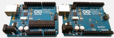
Arduino UNO R3 – Standard (left) vs SMD (right)
Both standard and SMD version work otherwise 100% identically – but you’ll see in the image above that the actual microcontroller (Atmel ATMEGA328) in the SMD version (right) is much smaller than the regular version (left).
Placing your Arduino board
When working with your Arduino, specially when power on (ie. the USB cable or the power connector is plugged in), make sure it’s laying on a non-conductive surface and keep metal/conducting objects away from the board to prevent unwanted shortcuts.
USB Cable
This should be your regular USB cable with a type A connector (male) on one side and a type B connector (male) on the other side. You’ll find this cable often used for printers and scanners, and some Arduino suppliers provide a cable with the Arduino board.
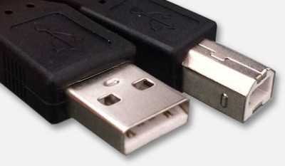
USB Cable with Type A and Type B connectors
Arduino Software
The required software can be downloaded from the Arduino Website for free and is available for Windows, MacOS X and Linux (32- and 64-bit versions).
Download the free Arduino IDE
In the past, I offered downloads directly from Tweaking4All.
Due to frequent updates of the Arduino IDE, I’ve remove these downloads and replaced it with this message.
Download the most recent Arduino IDE directly from the Arduino website.
Note for Linux users: You can use apt-get to download the Arduino software:
sudo apt-get update

sudo apt-get install arduino arduino-core
After downloading and installing the software, now start the Arduino application, which will look only slightly different on each Operating System, but the “core” view is the same for all (Well done Arduino team!). As usual the MacOS X menu is in the top bar of your screen, where as Linux and Ubuntu have their menu in the top of the application window.
Connect your Arduino NOW to the USB cable and plug the other end of the USB cable into your computer!
Note : During installation, appropriate drivers will be installed for the USB port as well, which work out-of-the-box for Linux and MacOS X. Windows users need to help the driver a little bit to get installed (more about this below).
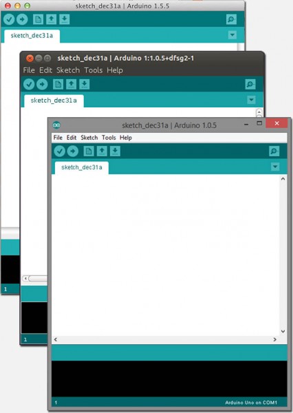
Arduino Software under MacOS X, Ubuntu and Windows
Drivers for Windows users
Unfortunately the drivers under Windows need to be installed manually (one time only) – it appears that the automatic detection fails to install no matter what you try.
Windows XP:
Go to “Device manager” (Right click “My Computer” or through the Control Panel) and find the “Other devices” “Unknown Device” and right click it and select “Update Driver“.
In the new window, select “Install from a list or specific location” and click “Next“.
In the next window uncheck “Search removable media” and check “Include this location in the search“.
Next click “Browse” and go to “C:\Program Files\Arduino\drivers“, click “OK“, and click “Next“.
Windows 7 and newer:
Go to “Control Panel” “Device Manager” and look either under “Ports” or “Unkown Devices” where you will find a device with a yellow exclamation mark.
Right click it and select “Update driver software“.
In the new window click “Browse my computer for driver software” and in the next window click “Browse” and go to “C:\Program Files (x86)\Arduino\drivers” (the ” (x86)” only appears in 64 bit systems) and click “Next“.
Windows in Virtual Machines:
While writing this article using virtual machines for Windows, it became apparent that these drivers do not work in a virtual machine (tried Parallels and VMWare).
Under normal circumstances this should not be a problem as the 3 most common Operating Systems are supported by the Arduino software.
Initial Configuration of Arduino Software
After installation (and installation of drivers for Windows users), we need to do some initial settings in the Arduino software.
(don’t forget to connect your Arduino to your computer!)
Windows users:
First we need to connect to the right device.
Open the menu “Tools” “Serial Port” and select the proper “Com” port (USB device), this will strongly depend on your computer, but it could be for example COM4. Most newer computers no longer have standard COM-ports build in, so in those cases this might even be COM1.
Next we need to set what type of Arduino board we’re using.
From the menu “Tools” “Board” select the Arduino board you have, in my case “Arduino Uno“.
Linux users:
First we need to select the right device.
Open the menu “Tools” “Serial Port” and select the serial device for the USB connection to the Arduino (on my Ubuntu setup this was /dev/ttyMCA0 , yours might be different).
After that we can set what kind of Arduino we’re using.
From the menu “Tools” “Board” select the Arduino board you have, in my case “Arduino Uno“.
MacOS X users:
Mac’s don’t have com-ports, so we need to select the right device port for our Arduino.
From the menu choose “Tools” “Port” and look for the something like this (if you have an Uno): /dev/cu.usbmodem1421 (Arduino Uno) and select it.
Next we need to pick our Arduino type from the menu “Tools” “Board“, in my case “Arduino Uno“.
Now that we have completed this, we’re ready to run our first application on any of these platforms.
Ad Blocking Detected Please consider disabling your ad blocker for our website.
We rely on these ads to be able to run our website.
You can of course support us in other ways (see Support Us on the left).
My First Arduino Project
Before we start: in Arduino a “program” is called a Sketch and a Sketch is written in C/C++. I would have prefered a language like Pascal but plenty of users will disagree with me on that one … definitely because of a lack of understanding of Pascal, but let’s not get lost in that discussion  …
…
Shortcuts …
A few shortcuts you’ll need to know about can be found in the illustration below.
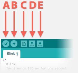
Arduino Software – Useful shortcuts
Useful Arduino Shortcuts
| Shortcut button |
Purpose |
| A |
Verify – Verify Code (or: just Compile code) |
| B |
Upload – Compile and Upload program to Arduino |
| C |
New – Create New Sketch |
| D |
Open – Open existing Sketch |
| E |
Save – Save Sketch |
After entering code or making changes, using “Verify” (A) is always a good thing to do. It basically compiles your code and reports possible errors.
To run your code on the arduino, the compiled code needs to be uploaded to the microcontroller. So the “Upload” button (B) compiles your code and copies the compiled code to the Arduino if compilation was successful. It basically combines the “Verify” function with uploading to your Arduino.
Basic Elements of a Sketch
With each sketch we have a few basic elements …
It’s good practice to properly comment your code. It will save you and others time deciphering where what happens.
Comments start with two slashes forward (//), anything after these two characters will be considered comments.
Commenst are ignored by the compiler and makes the compiled code not any bigger or smaller, but readability increases dramatically.
Alternatively you can place comments (spanning multiple lines if needed) between ‘/*’ and ‘*/’.
Comments can also be used to disable certain parts of code quickly without deleting the lines.
1
2
3
4
5
6
7
8
9
10
11
12
13
14
15
16
17
| // Single line comment
int led = 13; // Comment as last part of the line
// The next line uses comments to disable the code
// int led = 14;
/* This is a comment block on one line */
/* But comment blocks
can also span
multiple line */
/* Comment blocks can also be used to disable code even over multiple lines
int led = 13;
int MyVariable = 8;
*/ |
Pound or Hash statements (optional)
Hash (“#” or “Pound” like Americans like to call it) statements are compiler directives – we will not use these in our first project, but you will run into them with other projects. The compiler is the program that converts your text based program to executable code for the microcontroller.
Note : Compiler directives do not end a line with a semi colon (;) unlike normal statements.
You don’t always need them but with larger programs you’ll see the following 2 quite often …
LIBRARY INCLUDES
This statement will tell the compiler to include a library called “MyFile.h”, a C include file. The included file can be called a library – a file that holds functions that can be reused for different Sketches/Programs. Typically these library gear towards functions related to one particular use, for example a library to control LED strands, do special mathematical calculations or a library to control LCD display.
CONSTANTS
This statement defines “MyConstant” as the value “6”, which tells the compiler that every occurrence of “MyConstant” must be replaced by “6”.
The purpose of this is to write more readable code by using predefined constants (just the number siz doesn’t explain much), which is often done in the beginning of your code, making it easier to adapt code to a different value for this constant – instead of having to retyping that value throughout your code, you’ll only need to change it in this line.
Definition of global variables (optional)
Outside of all functions we can also define so called “global variables”, which are variables that are known all over the Sketch.
the value of such variable can for example be read or changed in the setup() and loop() functions – in contrast to a constant as we have seen in the #define example.
In the example below we define a variable called “MyVariable” which is supposed to hold an integer number, and we set that variable to 8.
Function: Setup()
This is mandatory in ANY program you write for your Arduino and is used to initialize certain settings before the actual “program” starts running.
Here one would for example set a particular pin to be an output pin.
The term “void ” in front of the function name only indicates that no return value is to be expected – a standard C declaration.
Function: Loop()
This is mandatory in ANY program you write and this is the part that keeps looping forever – a program on a microcontroller keeps running forever and start by powering on the microcontroller and stops by powering it off, unlike a desktop or laptop computer.
In this part of the code, one would for example toggle a pin ON or OFF.
Our first Sketch
Note : this example sketch can be found, with other examples, in the standard examples that come with the Arduino software.
In our first Sketch we will basically make a LED blink.
Simple and probably pretty silly when you think about it, but the purpose is to get familiar with your Arduino and not to right away build your version of the Mars Rover.
In this case we have the option to use an LED that can already be found on most Arduino boards: the LED connected to pin 13.
You can however decide, maybe as a second step, to connect an LED to pin 13 to see this with your own LED, we will illustrate that later as well.
The code:
1
2
3
4
5
6
7
8
9
10
11
12
13
14
15
16
17
18
19
20
21
22
23
24
| /*
Blink
Turns on an LED on for one second, then off for one second, repeatedly.
This example code is in the public domain.
*/
// Pin 13 has an LED connected on most Arduino boards.
// give it a name:
int led = 13;
// the setup routine runs once when you press reset:
void setup() {
// initialize the digital pin as an output.
pinMode(led, OUTPUT);
}
// the loop routine runs over and over again forever:
void loop() {
digitalWrite(led, HIGH); // turn the LED on (HIGH is the voltage level)
delay(1000); // wait for a second
digitalWrite(led, LOW); // turn the LED off by making the voltage LOW
delay(1000); // wait for a second
} |
As you can see, both setup() and loop() exist in this Sketch and it right away illustrates the purpose of both function.
Before running anything you’ll see the line int led = 13; which defines a global variable (known in setup() and loop()) called “led” with the initial value of “13”. One could change that value at a later time in either setup() or loop(), but in this example we are not doing this and using a constant (#define led 13) would have worked just as well.
In setup() we set pin 13 (the variable led) to OUTPUT, so it will be used as an output. Output is obviously not just used for LEDs but can also be used for a little buzzer, a motor, an LCD display, a servo etc. This in contrast with an input, which could be a switch, a light sensor, etc.
Once the initial setup() has been done, the Arduino will start the “program” in the loop() function and will keep repeating loop() until the end of times or until power dies.
The following steps are being looped:
Steps of our First Arduino Project
| Code |
Action |
| digitalWrite(led, HIGH); |
Set pin 13 (led) to HIGH – or in other words set it to +5V and the LED goes ON |
| delay(1000); |
Wait time in milliseconds, here 1 second (1000 milliseconds = 1 second) |
| digitalWrite(led, LOW) |
Set pin 13 (led) to LOW – set the voltage to 0V and the LED goes OFF |
| delay(1000); |
Wait time in milliseconds, here 1 second (1000 milliseconds = 1 second) |
OK now that we know what the Sketch will do, you can either load it from the Arduino examples menu (“Files” “Example” “01.Basics” “Blink“) or you can type the short version in manually (I removed all the comments):
1
2
3
4
5
6
7
8
9
10
11
12
| int led = 13;
void setup() {
pinMode(led, OUTPUT);
}
void loop() {
digitalWrite(led, HIGH);
delay(1000);
digitalWrite(led, LOW);
delay(1000);
} |
If you look at the shortcut buttons we mentioned earlier: after entering the code, click the “Upload” button.
If no red messages appear in the black area at the bottom of the Arduino window, then you’re good to go and you’ll see a tiny LED on your Arduino blink …
(during upload two LEDs, under the LED connected to pin 13, will blink briefly)
Arduino Uno: LED on pin 13
Expanding your First Project with extra “Hardware”
Our first project uses only the Arduino board. The LED to pin 13 was simply there for simple purposes.
Now we will expand a little by adding an external LED. The trick we’re going to use here is not exactly the way it should be done, but we can actually plug an LED straight on the board.
Caution …
Normally you will have to put a small resistor (say 330Ω) between the LED and the power, but for a very short experiment this will work.
So do not take this as a good example of how things should be done – I just wanted to keep it simple and avoid the need for a breadboard.
See the correct LED connection example in the How to use a Breadboard article.
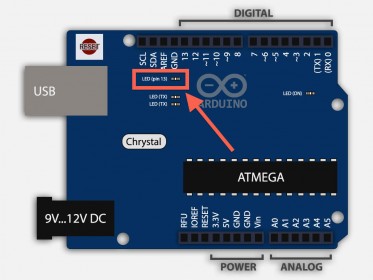
Grab an LED and look at your Arduino board. Find pin 13 (upper left corner in the illustration above) which will serve as a plus. You will see a pin next to it called GND (Ground)whcih for simplicity reasons could be called: minus.
Now look at your LED and determine which pin is the Kathode and slide the Cathode pin into the connection that says GND and the other pin (Anode) in the connection that sais “13”.
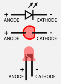
LED Pinout
You can even do this while your first program is running – it is however good practive to first power the Arduino down (unplug the USB cable).
Be aware though that you can only use this for a short time, you’d like to avoid burning out the LED. As you can see in the photo below: the LED lights up pretty bright.
Click on the photo to see the pins in more detail.
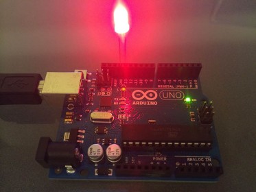
Arduino UNO with an extra LED
That concludes our first experiment, and I’ll try to post more Arduino articles in the future …


Comments
There are 4 comments. You can read them below.
You can post your own comments by using the form below, or reply to existing comments by using the "Reply" button.
Brilliant! Very nice explanation, easy to understand and solid background knowledge.
Xavier
Thanks Xavier for taking the time to the post your very nice compliment!
I’m glad this article was useful to you!
hans
[…] Sources: …https://www.tweaking4all.com/hardware/arduino/first-arduino-project/… […]
[…] Sources: …https://www.tweaking4all.com/hardware/arduino/first-arduino-project/… […]